


Support this website by joining the Silver Rails TrainWeb Club for as little as $1 per month.
Click here for info.


This website has been archived from TrainWeb.org/cior to TrainWeb.US/cior.
When I finally arrived at building the CIOR's Dunreith District I knew I had to build the massive viaduct that stretched over the town of Cambridge City, Indiana. The only thing I ever saw on the viaduct where weeds, by the time I got down there the trains had been removed and only rusty rails remained. In all my years of visiting the little hamlet of Cambridge City, I never grabbed that picture of it I always wanted. By the time I finally got to it, the viaduct was nothing more then a long pile of rubble and some weeds. The approach from the west (Indianapolis side) was still in place, and left some feel of the shear size of the viaduct.
So, what to do. I was left with a few ideas in the realm of casting my own plaster molds and hand carving the entire thing, looking for a ready made or kit of the viaduct, either online or via mailorder. Another idea was to commission an artist/carver to reproduce it, but that had two failing things: COST & ACCURACY. The fact remained, without a picture of the actual viaduct I was left to nothing more then memory. So I searched and searched, turned over every possible leaf I could, then just sorta put it on the back burner. Ironic as it was, I was just about to use the MicroEngineering tall viaduct, when I did a google search on PRR stone viaduct and what should I find, but "www.modelrailroadstoneworks.com" and after some looking at the pictures it hit me, this is it. The semi circular stone arch viaduct was a dead ringer for the Cambridge City viaduct. I had always thought that the viaduct at Cambridge City was probably close to a "standard plan" from the PRR books.
I decided to email the owner of the "modelrailroadstoneworks.com" to find out what could be done to extend the stock version to a closer distance of the real thing. After exchanging emails, it was decided I could use just one of the extension kits and get what I needed. Now, in real life the span was roughly 900' or so, but that was longer then the 4 feet I had set aside for this task. I sent the check to modelrailroadstonework.com and in less then 2 weeks I had a freshly poured viaduct, that came in 2 boxes. I slowly unpacked the boxes, and must admit, I was more like a kid on Christmas morning, only reminding myself its plaster and be careful. Once it was unpacked I set out and measured it to make sure how much room I had. With that dimension in hand, I finally went to the basement and removed a 5' section of benchwork, so I could lower it and fit the viaduct scene in.
When the benchwork was removed I layed out the viaduct on the plywood base that would become its home. I decided to make the viaduct itself removable from the rest of the layout without to much damage. Being honest, I don't think this will be the last layout I will build, and the viaduct was to much money and effort just to send to its demise! So, once it was layed out I decided to let it set and get the outdoor work done. The warm season was upon us and well, yard work called! So there it sat, everytime I walked down into the basement for something, it just sat there looking at me.
Finally, I decided to start the preliminary work on the viaduct. The first order of business was the cut, sand and fit each piece to the other, slow and steady a little at a time. I decided I would only work on it as much as I felt and nothing more. Thankfully during this normally dry time of year, we have had a great rainy season. So, with the rain has come more time to work on the viaduct. Finally, after everything was test fit, I started the assembly process.
Tools needed:
-Sandpaper (various grit) and open mesh sanding paper (the kind drywallers use)
-Flat fine tooth jam saw (specialty saw, can be purchased at lowes)
-Dull flat blade Xacto knife
-Used hacksaw blade (tape one end with electrical tape not to cut your hand!)
-Fine 1-1/4" drywall screws
-White school glue
-Drywall Joint Compound
-Phillips head screwdriver
Now its important to take your time here, obviously you probably need to have a power miter saw, to aid in building the support structure on one end. Start by taking your first measurement, this will be the length from the backside of the land abutment to the bottom of the pier. Basically this should come somewhere in the ballpark of 10-1/4" (anywhere in that ballpark, as low as 10"). Once you have that, you will need to attach the back brace to it, its simple to just use 1x4" boards and make the brace.

Once you have the brace made, you will need to cut a flat 90degree L shape out of the backside of the abutment (it has a slight angle, so make it flat).

Now, rough fit the first pier and first half arch against the abutment, make sure everything is aligned. Once you have it in place, lay the arch piece aside and return to the abutment, now, take a small drill bit (smaller then the diameter of screw you are using) and drill a hole into wood and plaster on each side of the brace. Make sure the hole is deeper then the screw is long, make sure that you drill slow and TAKE YOUR TIME, this is plaster and it can crack and break.

Remember this, the screws that you are using now are only for the initial support of the structures, they will be removed or become redundant once the entire structure is up and connected. I don't recommend using an adhesive (i.e. liquid nails or construction glues) as once they dry, you are almost certain to break the piece if you need to move or reposition it.

Once you have this main abutment piece set in place and locked down its time to start laying out the rest of the piers.

This is probably the toughest part, as you have to be 100% correct in your measurements.
Set in each arch and pier, once they are level, then take a sharpie marker and draw the base of the pier on the plywood subbase. Atleast draw the front and both sides, as this will give you a third reference point. Once you have this done, then remove the pier and arch and drill down through the plywood in the middle of where the pier would be. Once you have this, set the pier on the plywood inside the marks and drill upward into the plaster casting pier. If you want, you can do as I did and once you hit the plaster on both holes, remove the drill and pier and drill the pier independantly of the plywood. Like I said before, make sure you drill the hole deep enough!
Once you have the first pier drilled, now insert the drywall screw and screw the base pier into the plywood. Be careful, you don't want to strip out the plaster or break it. So, Take your time with this step.
When you have the first pier in place, it is just a matter of "do the same for the remainder". Just make sure you have everything lined up as you go, it is easier at this point to go back and make corrections, rather then having to undo everything.
So now we have all the piers in place, time for some glue. I used plain ole white school glue, I used a foam brush to apply it. Now, I only used the white glue during the fitting process and not for the final bonding agent. I worked one pier and arch at a time and moved from right to left. (your approach will vary, you need to decide what works best for you. I am right handed and it was just better to work that direction). I worked until I got to the left abutment and stopped. Once I had things the way I wanted, I then began to take everything apart again. This seems like one more step then need be, but I found that any mistake will still be correctable. Once you start the next process there is little to be done to correct matters.
Final Assembly OK, now its joint compound time. I worked with a 1" knife and a large bucket, but any 5lbs bucket of joint compound will do. Spread the joint compound out evenly. We have all made PB&J and its not much harder then that. Just be careful that you don't push it into detail areas of the viaduct. (the nice thing is you can carve out the areas if you do accidently get it into the cracks and carved areas.) Once I had all of them in place and the initial layer of joint compound in, I used masking tape and embedded it into the joint compound on the top of the viaduct (where the two sections join) you could use drywall tape, but I couldn't find any in the house, so it was using what I had.

Once this step is done, its just a matter of cleaning up for the night and letting it set. You want to let things cure at this point, don't be down messing around with it, because you will be prone to knocking something out of place, its just the way luck works.
The following day (atleast a day later, give it 24 hours or so to dry) you will need to work on building the final abutment. This side will just fit as needed, so you won't have to set it perfect. You will want it to set with the rest of the viaduct, so build its support accordingly.
With everything set up, the other end attached, its time to level out the top for the homabed. I suggest you seal the homabed with a good sealer of some kind before this step.
The way I attempted the task of leveling out the top was to use joint compound to for a self leveler and to also hold it in place. Once that was set I used white glue to hold the joints together.
Once you have the top on its time to put on the top course of blocks, I used white glue and tape to hold them, give them 24 hours to dry. Once they are dry you will need to remove the tape and fill in the gaps with plaster or filled. Make sure you take your time and fill in all the gaps. Since the backside of the viaduct won't be seen on the layout, I won't go into complex detail, but atleast take the time to do a nice trim out and clean the corses.

In this picture you can see the homabed and top course of blocks in place. Also notice that all the piers are finished off too. This process took 2 days, but has turned out to be well worth it.

The nice thing about this viaduct kit is the ability to make things fit. It took alot of "ahead of time" work, but it made the final assembly go fairly quick, and not nearly as much corrective work to be done.
Here is a view from the backside of the viaduct. This side won't be viewable at ALL, but I still felt the need to finish the backside off anyway. (note, its not nearly as complex in detail, but it still makes a difference).

The funny quirk about this viaduct was the need to slightly angle the final arch. It needed a full 1/2" of forward rotation, and this left somewhat of a hefty gap to fill in. But, after 2 fill and 1 final dress coat, it looks fine, besides you won't notice it anyway.

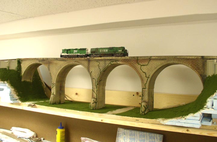
Work has progressed since the last update. The viaduct has been painted, a special mix had to be made to get the right color, it turned out well, and I think makes a fitting equal to the real deal.

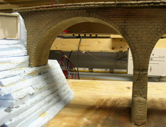
This is a close up view of the arch and weathering. The green on the pier is a marker paint to guide me when applying the ivy. It also serves as a background to fill it in as needed. As you can see, the foam has been cut and placed awaiting drywall mud. Since I took this picture the first coat of mud has been placed and I should be getting the final layers on, depending on the weather.
The ballast came in today, and I started the ballasting to get that part out of the way. (More info on the ballast later on). As you can see, I was able to get the proper kink into the viaduct at the west end. In order to do this and make things look right underneath, I had to sand some off on the front edge and then add mud to fill it in. I also used some styrene spacers. Hopefully this will come out right once the viaduct is put in place.

Things have really progressed since I last updated the construction of the viaduct. Foam has been put in place and carved, then several applications of joint compound. Although I didn't take pictures of this, I mixed paint into the joint compound to give it a dirt color. Once I had this carved and looking right I added in the grass, and made the vines. I guess I will take some time off from working on the viaduct project, its been very time consuming and other projects are calling. So, I will keep everyone advised to when this project gets started up again.
--Check back to see the finished viaduct!!!--
WARNING-Legal: This is my opinion and not that of the manufacturer of the product. This is only meant to be a helpful "how to" and is not direct instruction. Use this info at your own discretion. We make no guarantee how things will turn out on your project. We are not responsible for errors or mistakes/accidents that might occur.


About Us |
Contact Us |
Advertise With Us |
Sign up for our FREE e-Newsletter!
 View Stats
| Page updated: 05/26/2021
| Version 2023l21b
| Links
| ©2015-2024 Silver Rails
View Stats
| Page updated: 05/26/2021
| Version 2023l21b
| Links
| ©2015-2024 Silver Rails
Support this website by joining the Silver Rails TrainWeb Club for as little as $1 per month.
Click here for info.