London Underground Track and Traction Current
Some information about the design of track used
on the London Underground and the traction power supply system.
Contents
Track - Current Rails - Why 4 Rails? - Track in Tube Tunnels - Rail
Greasing - Ramps and Crossings - Traction Current Supply System - Sectionalisation Gaps - Rail
Gap Indicators - Getting Gapped - Tunnel Telephone Wires - Traction Current Sections - Shoes & Shoegear - Tunnel
Lights - Current Supply in Depots - The Power of the Arc
The London Underground has always used the old
UK standard bullhead rail weighing 95 lbs/yd and wooden sleepers. Only in the last
few years has there been a concerted effort to convert the track to flat bottom rail like
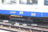
the rest of the world. The photo below shows the standard LU bullhead track which
can still be seen all over the system. It also shows clearly the 3rd and 4th
insulated rails used for the LU traction current system.
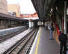 Fig 1: Photo of standard London Underground track at
Surrey Quays (East London Line) Fig 1: Photo of standard London Underground track at
Surrey Quays (East London Line)
Click on the image for the full size view
and description.
To the Top of this Page
All London Underground Lines (including the W & C)
operate at 630 volts DC using third (positive) and fourth (negative) current rails.
The current rails are positioned so that the contact surface is higher than the running
rails. This allows the collector shoes on the trains to pass over the running rails
without touching them. The positive rail is 3 inches higher than the running rails,
while the negative rail is 1.5 inches higher. The positive insulators are thus twice
the height of the negative ones and therefore have about twice the earth leakage
resistance, so the voltages are set with a proportional disparity between the positive and
negative voltage levels. The positive rail is at a potential of 420 volts above
earth and the negative rail at 210 volts below earth.
In this view above of Surrey Quays (East London Line) the
arrangement of current rails is clearly seen. The negative rail is mounted centrally
between the two running rails. The positive rail is mounted outside the running
rails. Current rails are of a heavier cross section than running rails in this view.
Note how the positive rail is positioned away from the platform side of the track.
The standard position for the positive rail is usually on the left hand side in the
usual direction of travel.
To the Top of this Page
The London Underground uses the four rail system for two main
reasons. Firstly, it was originally required by the government to limit the voltage drop
along the line to 7 volts. This was intended to reduce problems caused by stray
currents causing electrolysis affecting utility pipes and cables. Whilst this did
not affect the street tramways, whose vehicles were not heavy current users, the currents
drawn by trains could cause difficulties. The solution was either to provide heavy
return cables and boosters or to use a fourth rail. The fourth rail was chosen,
partly as a cheaper option and partly for signalling reasons. As direct current
track circuits were to be used to control signals, an insulated return system for the
traction current was an effective way of separating the two systems. Nowadays, this
is not so much of a problem as all track circuits are AC.
It is interesting to note that it is also possible to
maintain a service if one pole of the supply is earthed whereas, if a three-rail supply
system becomes earthed, the sub-station circuits breakers will detect the short circuit
(usually) and the power will be switched off. On the Underground, if there is an
earth, it will be detected by special monitoring equipment and an alarm initiated in the
line control room. The cause is then tracked down to, usually, a defect on a train,
a current rail problem or the lift/escalator supply, where this is still 630 volts
DC. Modern trains on the Underground are provided with on-board earth fault
detectors.
It is important to ensure that positive and negative earths
do not occur in the same traction current section, as this can give rise to high current
"loop circuits", which have been known to break down cable insulation and cause
fires. See also Sectionalisation Gaps
below.
Curiously, the Bakerloo was opened (in March 1906) with the
polarity of the current rails reversed. There were problems with leakage of the
positive rail into the cast iron tunnel segments so the positive side used the centre rail
and the negative used the outside rail. This was exacerbated by the fact that the
line was supplied through the same system as the District. The problem was solved on
the Piccadilly and Hampstead lines by concreting the lower part of the segments near the
track. The Bakerloo was converted to normal in 1917, when the line's supply was
modernised.
To the Top of this Page
Tube tunnels use a different cross section of current rails
as seen below.
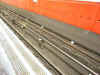 Fig 2: Photo of London Underground track at
a typical tube station with a suicide pit. Fig 2: Photo of London Underground track at
a typical tube station with a suicide pit.
Click on the image for the full size view
and description.
Here, in this deep level tube station, the current rails are
of lighter section than the running rails, which have been upgraded to flat bottom
rail. The white porcelain insulating "pots", which carry the current
rails, can also be seen.
In tube tunnels, the rails are mounted on small wooden blocks
set into concrete. In the centre of the track, a drainage trough is provided and is
filled with ballast to reduce noise. In stations, as shown above, a "suicide
pit" is provided between the running rails to assist with the removal of bodies from
under trains. In the tunnels, a shallow pit is provided between the rails and is
filled with ballast to provide sound deadening and drainage. Renewing track in
tunnels is a slow and difficult process due to the need to drill out the blocks and renew
the concrete. It usually requires a speed restriction of 10 mi/h while work is in
progress.
To the Top of this Page
Have you ever wondered what the screeching noise is that you
sometimes hear when a train goes round a curve? It's the wheel flanges scraping
against the inside edge of the outer rail of the curve. The best way to get rid of
the noise and reduce the wear on wheel and rail, is to lubricate the wheel flange.
This is done with either track mounted or train mounted lubricators.
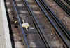 Fig 3: Track mounted flange greaser located at Rayners
Lane. Fig 3: Track mounted flange greaser located at Rayners
Lane.
Click on the image for the full size view.
London Underground uses track mounted lubricators and the
photo above shows one type commonly seen around the system. The problem with the
track mounted type is that is has to be refilled regularly and carefully adjusted to
ensure the correct amount of grease or oil is picked up by the wheel.s is not easy to
achieve. One Tuesday morning some years ago, following a Public Holiday weekend,
almost the whole of the Victoria Line fleet was disabled with flatted wheels caused by
emergency braking at stations. The trains had picked up too much grease from a badly
adjusted flange lubricator and had skidded at the following station trying to stop in the
right place.
Train mounted lubricators are usually in the form of a stick
of lubricant mounted on the bogie and applied to the wheel under light pressure.
They are easier to maintain than track lubricators and are generally favoured on new
railway systems. Some recent LU stocks are fitted with these.
To the Top of this Page
The trackwork required for the LU fourth rail system can be
very complicated. The following example of the scissors crossover at Ealing Broadway
shows just what is involved.
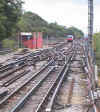 Fig 4: Crossover at Ealing Broadway showing
current rail gaps and ramps . Fig 4: Crossover at Ealing Broadway showing
current rail gaps and ramps .
Click on the image for the full size view
and description.
The current rails have to be broken wherever
there is any sort of obstruction which could come into contact with the shoes of the
train. This can be best seen above where then ends of the current rails are painted
white to assist staff walking the track. Where there is a risk of the shoes touching
the running rails or any obstruction, a wooden ramp is provided to assist in lifting a low
or loose shoe clear. This is shown in the photo below (Moorgate, Metropolitan) where
a trainstop requires a break in the positive current rail. The trainstop is
protected by wooden ramps. You can see that the ends of the current rails are also
ramped to allow a smooth passage for the shoes as they run on and off.
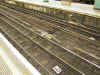 Fig 5: Current rail gaps provided at Moorgate for terminal
protection trainstops . Fig 5: Current rail gaps provided at Moorgate for terminal
protection trainstops .
Click on the image for the full size view
and description.
To the Top of this Page
Traction current is supplied to lines in
sections. Sections can be anything from less than one kilometre to several
kilometres long. Sections are separated by gaps in the current rails where the
sub-stations are located. Each sub-station normally feeds the two sections on either
side of a gap. The general arrangement of traction current supply on London
underground is shown in the diagram below.
Fig 6: General arrangement of traction current supply on London Underground .
A section which is fed by a sub-station at each
end is known as double-end fed. A section, usually towards a terminus, with a feed
at one end only is known as single-end fed.
At various places along the line, section
switches (Fig 6) are provided to allow small sections of line to be isolated from the
supply. At a terminus, section isolating switches are provided to isolate the
platform sections from the supply, useful when necessary to deal with a power circuit
electrical fault on a train. Section switches are usually manually operated on LU.
Many more modern systems allow remote control of section switches.
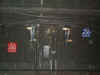 Fig 7: A pair of unguarded section switches mounted on the tunnel
wall near Camden Town, Northern Line. Photo by Donald McGarr. Fig 7: A pair of unguarded section switches mounted on the tunnel
wall near Camden Town, Northern Line. Photo by Donald McGarr.
Click on the image for the full size view.
Although traction current is intended primarily
for trains, there are some escalators still fed from the traction supply and a few
heavy-duty ventilation fans and lifts. LU has to restrict the levels of current
regenerated by trains (where available) because, if it is too high, the additional voltage
will make the escalators run faster than they are supposed to and may cause trains to
reach too high a speed.
To the Top of this Page
Sectionalisation gaps are similar to normal
substation gaps in that they separate the current rail feeds into a pair of adjacent
sections but the length of the gap is longer than the traditional gap. This is so
that the shoes of a car cannot form a "bridge" between one section and the
next. It avoids the risk of a train causing a section with current off being
temporarily made live from the adjacent section through the shoes and on-board cables of a
car creating a link.
Sectionalisation gaps are also arranged so that
the substation connections are entirely isolated from each other so that earth faults on
one section are not transmitted to the adjacent section. Earth faults are caused
when one pole of the system becomes connected to earth, often because of an insulation
fault on a train or escalator, or because a current rail is linked to the ground with a
metal object. If a positive earth fault occurs in the same area as a negative earth
fault some distance away, very high currents can be generated. Originally, most of
the London Underground current supply system was linked through substations. After a
couple of serious incidents in the late 1950s, where high fault currents generated fires
on board trains, the idea of sectionalisation was introduced and the system was de-coupled
at a number of strategic locations. On lines built since that time (Victoria and
Jubilee extensions) sectionalisation has been provided at all substations.
To the Top of this Page
Each sub-station gap is provided with an
indicator showing three red lights if the current is off on the section ahead.
Sites with poor visibility are provided with rail gap repeaters with three yellow lights.
 Fig 8: This photo (by Donald McGarr) shows a rail gap
indicator (RGI) in the tunnel at Camden Town. Just beyond is a 20 mi/h permanent
speed restriction sign. Fig 8: This photo (by Donald McGarr) shows a rail gap
indicator (RGI) in the tunnel at Camden Town. Just beyond is a 20 mi/h permanent
speed restriction sign.
Click on the image for the full size view.
If the RGI is illuminated to show three red
lights, as shown below, it represents a stop signal. The driver of an approaching
train must stop or, if unable to, he must coast over the gap until the whole train is
clear. This is to prevent current being transferred from the live section to the
dead section by the shoes on the train. Rail Gap Indicators are not provided with
trainstops.
To the Top of this Page
One of the most embarrassing incident to happen
to a driver is to get his train "gapped". This happens when the train
stops without any of its current collection shoes connected to the current rails.
The only two ways out of the problem is either to push the train onto the nearest current
rails or to make use of long cables (called gap leads) which can be used to connect a
socket on the train to shoes at the other ends of the leads which are then placed on the
rails. Both procedures will cause a long delay and leave the driver with a lot of
explaining to do.
The worst locations for gapping are at the
entrances to depots. There are always lots of breaks in the current rails because of
all the point and crossing work. One of the most dangerous is at the south entrance
to Neasden Depot. If you had a short train, it was best never to stop
and to hope that the shunter was available to give you the road number and stop point as
you ran in. If he wasn't there, you just ran in and stopped where you knew it was
safe. You could not risk stopping and gapping your train across both Jubilee tracks
and the southbound Metropolitan Line.
To the Top of this Page
London Underground tunnels are fitted with
Tunnel Telephone Wires. These are uncovered wires used to switch off traction
current in emergency. A current of 5-10 volts runs through the wires and energises a
relay at the local substation(s). If this current is lost, the relay is de-energised
and the circuit breaker opens at each end of that current section. This cuts off the 630v
traction current feed. Even through the relay may then become re-energised, the
circuit breakers will remain open until reset.
The relay can be de-energised through various
means such as the train operator pinching and rubbing the two telephone wires together or
the the operator connecting a portable handset to the wires. This will then also
allow him to speak to the Line Controller. Other connections on the wires in that
section include tunnel telephones and section plungers provided at stations.
The Line Controller has a remote facility (a
bank of switches on his desk for each traction current section on the line) which allows
him to effectively short circuit the tunnel telephone wires in the same way as the T/Op
shorting them. Defective tunnel telephone wires/equipment will also result in the
relay becoming de-energised. If the equipment cannot be reset due to a fault on the
tunnel telephone circuit, the circuit can be overridden. A "T" board will
then be displayed to drivers at the relevant stations to tell the train operators that the
tunnel telephone wires are not working.
With the advent of train radio, the tunnel
telephone wires are rarely used to switch off traction current these days. However,
they do offer an alternative means of contact to the Line Controller in an emergency if
there is a problem with the train radio. Traction current will be switched off when
the handset is used but the Line Controller can soon arrange for it to be switched back on
again and using the tunnel telephone wires in this way will usually mean less of a delay
than trying to contact somebody by other available means.
Sometimes, too many trains in a section will
cause current to go off. The more current drawn in a section, the more the traction
current voltage drops. As a consequence, some equipment on a train may also cut, out
MGs/MAs for example. Some black spot where this happens are between South Wimbledon
and Morden (Northern), Russell Square and Holloway Road and Wood Green to Southgate,
(Piccadilly Line) and Baker Street to Finchley Road (Met.). A favourite for South
Wimbledon to Morden in 1938 Stock days was when trains were queuing up to get into Morden
and it was nothing unusual to put the handle into motoring and find the tunnel lights come
on, put it back to off and the lights go out. Traction current wasn't lost, but the drop
in traction current voltage was sufficient that the tunnel lighting relays couldn't remain
energised and thus the lights came on. From information posted by Roger Mather,
uk.transport.london, May 2000.
To the Top of this Page
Listed below are the locations of the traction
current sections for some lines on the Underground. Substation gaps (dividing the
two sections) are located where the feed from the substation goes to the current
rails. Generally, the traction current section (or subsection as it is often known)
is named according to where it is fed from and the direction of travel, e.g. Stockwell to
Elephant & Castle NB. Although not a substation location, Kennington CX branch
is divided up between Lambeth South and Lambeth North thus, Lambeth South-Kennington SB,
Kennington Loop, Kennington-Lambeth North NB. Substations shown in capital letters
have Sectionalisation gaps.
Sectionalisation gaps were introduced in a
response to two serious incidents which occurred in 1958 and 1960, when earthing problems
caused trains fires on the Central Line at Redbridge and Notting Hill Gate. The
cause was due to a positive earth on one part of the supply system and a negative earth on
another. The resulting high current loop was sufficient to break down the insulation
on vulnerable parts of the trains in question. To reduce the risk on a
re-occurrence, the power supply system was "sectionalised" into groups of
sub-stations and long gaps provided to separate them. The long gaps prevents the
shoes on a train from bridging the gap and transferring a fault from one part of the
system to another.
Jubilee Line
Traction Current Sections
Stratford-Stratford Market depot
Stratford Market depot-Canning Town
Canning Town-North Greenwich
North Greenwich-Canada Water
Canada Water-Redcross Way
Redcross Way-Waterloo
Waterloo-Green Park
Charing Cross-Green Park
Green Park-Hays Mews (Mayfair)
Hays Mews-Baker Street
Baker Street-Finchley Road
Finchley Road-Kilburn Exeter Road
Kilburn Exeter Road-Willesden Green
Willesden Green-Neasden
Neasden-Wembley Park
Wembley Park-Preston Road
Preston Road-Queensbury
Queensbury-Canons Park
Canons Park-Stanmore |
Central Line Traction Current
Sections West Ruislip-Ruislip substation
Ruislip substation-Northolt
Northolt-Greenford
Greenford-Brentham
Brentham-Park Royal
Ealing Bdy-Park Royal
Park Royal-Wood Lane
Wood Lane-Notting Hill Gate
Notting Hill Gate-Bond Street
Bond St-Holborn
Holborn-Liverpool Street
Liverpool Street-Bethnal Green
Bethnal Green-Bow
Bow-Leyton
Leyton-Leytonstone
Leytonstone-Redbridge
Redbridge-Newbury Pk
Newbury Pk-Hainault
Hainault-Roding Valley
Leytonstone-South Woodford
S Woodford-Roding Valley
Roding Valley-Loughton
Loughton-Epping |
Northern Line Traction Current
Sections Morden - South Wimbledon
South Wimbledon - Balham
Balham - Clapham Common
Clapham Common - Stockwell
Stockwell - Elephant& Castle
Elephant& Castle - Old Street
Old Street - Euston (City)
Euston (City) - Camden Town
Camden Town - Kentish Town
Kentish Town - Highgate
Highgate - East Finchley
East Finchley - Finchley Central
Finchley Central - Woodside Park
Woodside Park - High Barnet
Clapham Common - Lambeth
Lambeth - Embankment
Embankment - Leicester Sq.
Leicester Sq. - Euston (CX)
Euston (CX) - Belsize Park
Belsize Park - Golders Green
Golders Green - Hendon
Hendon - Burnt Oak
Burnt Oak - Edgware |
Piccadilly Line Traction Current
Sections Hatton Cross - Hounslow East
Hounslow East - Northfields
Northfields - Acton Town
Rayners Lane - Sudbury Hill
Sudbury Hill - Alperton
Alperton - North Ealing
North Ealing - Acton Town
Acton Town - Chiswick Park
Chiswick Park - Ravenscourt Park
Ravenscourt Park - Barons Court
Barons Court - Earls Court
Earls Court - South Kensington
South Kensington - Hyde Pk Corner
Hyde Pk Corner - Dover Street
Dover Street - Leicester Square
Leicester Square - Russell Square
Russell Square - Holloway Road
Holloway Road - Manor House
Manor House - Wood Green
Wood Green - Arnos Grove
Arnos Grove - Southgate
Southgate - Cockfosters |
| Metropolitan Line Traction Current
Sections Aldgate - Moorgate
Moorgate - Charlton Street
Charlton Street - Baker Street
Baker Street- Bouverie Place
Bouverie Place - Notting Hill Gate
Notting Hill Gate -
Baker Street - Royal Oak
Royal Oak - Shepherds Bush
Baker Street - Finchley Road
Finchley Road - Willesden Green
Willesden Green - Neasden
Neasden - Preston Road
Preston Road - Harrow on the Hill
Harrow on the Hill - Rayners Lane
Rayners Lane - Eastcote
Eastcote - Ickenham
Ickenham - Uxbridge
Harrow on the Hill - Northwood
Northwood - Croxleyhall
Croxleyhall - Chalfont and Latimer
Chalfont and Latimer - Chorleywood
Surrey Docks (ELL) |
District Line Traction Current
Sections
Putney Bridge - Earls Court
Acton Town - Chiswick Park
Chiswick Park - Ravenscourt Park
Ravenscourt Park - Barons Court
Barons Court - Earls Court
Earls Court - South Kensington
South Kensington - Victoria
Victoria - Embankment
Embankment - Mansion House
Mansion House - Tower Hill
Tower Hill - Whitechapel
Whitechapel - Campbell Road
Campbell Road - Plaistow
Plaistow - East Ham
East Ham - Upney
Upney - Heathway (Dagenham)
Heathway (Dagenham) - Hornchurch
Hornchurch - Upminster |
Victoria Line Traction Current
Sections Brixton - Stockwell
Stockwell - Gillingham Street
Gillingham Street - Dover Street
Dover Street - Coburg Street
Coburg Street - Cloudesley Road
Cloudesley Road - Drayton Park
Drayton Park - Manor House
Manor House - Seven Sisters
Seven Sisters - Forest Road
|
Bakerloo Line Traction Current
Sections Elephant & Castle to Embankment
Embankment to Oxford Circus
Oxford Circus to Baker Street
Baker Street to Kilburn Park
Kilburn Park to Queens Park
|
Some information supplied by Donald McGarr,
3518+3227 and romic in uk.transport.london July 2000.
To the Top of this Page
The current is collected by shoes attached to
the trains as shown below on a 1973 Tube Stock motor car at Acton Town.
 Fig
9: Equipment provided on shoebeam of 1973 Tube Stock car. Fig
9: Equipment provided on shoebeam of 1973 Tube Stock car.
Click on the image for the full size view.
The positive shoe is sitting on top of the
current rail. There is a similar negative shoe out of sight under the bogie.
The support for the positive shoe is a laminated wooden beam hung from the axleboxes,
known as a shoebeam. There is also a shoebeam for the negative shoe but this is much
smaller and is mounted between the motor case and the bogie headstock.
Shoes rely on gravity to provide contact.
They are not sprung. They require careful inspection for wear at regular intervals
and have to be gauged to ensure they are not too high (poor contact) or too low (risk of
fouling something on the track). Negative shoes, being only 1.5 inches above the
running rail, are particularly prone to gauge defects and special "low negative shoe
detectors" are provided at certain depots around the system. An alarm is
sounded if a train is detected with a low negative shoe and it will not be allowed into
service until inspected.
Shoes can be lifted by train crew if it is
required to isolate a car from the current supply. Crews are supposed to know which
cars are fed from which shoes, but they have to lift shoes so rarely, it is difficult for
them to remember. On older stocks, the shoes are lifted by ropes provided inside the
car at suitable points. Once shoes are lifted, it is only possible to lower them
from under the train, preferably in the depot. The 1995/6 Tube Stocks are equipped
with push button shoe lifting and lowering control.
To the Top of this Page
London Underground tunnels are provided with
lighting. Over the last few years, there has been an upgrade programme which has
seen a big improvements in the lumination available in tunnels. The programme was
originally inspired by a number of difficult evacuations, made more so by the poor
lighting conditions. There was also the added benefit of better working conditions
for maintenance staff.
Tunnel lighting is powered from the LUL 400 V AC
lighting main, not the 600 V DC traction supply. A relay controlled circuit senses
the status of the DC supply and switches the tunnel lighting/power automatically when the
traction current is *off*. There's also a manual switch at headwalls, to turn on
tunnel lighting in emergencies.
Traction current can be turned off by train
crews in the tunnel by pinching together the two bare copper wires seen at window level in
all LU tunnels. A handset, provided on the train, can also be connected to these
wires to allow the train crew to speak to the controller.
Including a response from Furry to question
in uk.transport.london, 23 August 1999.
To the Top of this Page
Depots normally have their own sub-stations. Inside
most sheds, there are no current rails. Trains are therefore supplied through
overhead trolley leads, which are plugged into a "receptacle box" (a socket)
provided at the side of (usually) motor cars.
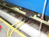 Fig 10: Overhead lead in receptacle box on 1973 Tube
Stock car. Photo by Tube Troll. Fig 10: Overhead lead in receptacle box on 1973 Tube
Stock car. Photo by Tube Troll.
Click on the image for the full size view.
The trolley runs on a two-rail track suspended at roof level
between each track. The two rail provide positive and negative current for the
leads, which hang down from the trolley. A special plug on the end of the leads is
placed in the receptacle box to provide 630 volts DC for the car concerned. Modern
stocks (199x Tube Stocks) have switches which prevent the shoes becoming live when an
overhead lead is plugged in.
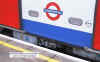 Fig 11: Shed receptacle on 1995 Tube Stock car. Fig 11: Shed receptacle on 1995 Tube Stock car.
Click on the image for the full size view.
Fig 12 shows the overhead lead inserted into the receptacle
box on the car. The box has a spring loaded lid to keep out water and dust while the
train is in service. A rope is provided to allow the trolley to be pulled along the
side of the train. In some cases the rope is tied to the train while it is driven
slowly along under power. Hammersmith Depot does this as a regular
practice.
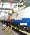 Fig 12: Overhead lead inserted on 1973 Tube Stock car
in Cockfosters Depot. Photo by Tube Troll Fig 12: Overhead lead inserted on 1973 Tube Stock car
in Cockfosters Depot. Photo by Tube Troll
Click on the image for the full size view
Note that Fig 12 shows ON and OFF indicators at
roof level to show where the overhead trolley track is live. These are recent
additions, imposed by recent Electricity at Work Regulations.
Elaborate precautions are taken to ensure that the leads are
not withdrawn while the train is drawing power, particularly traction power. A
number of incidents have occurred in the past where receptacle boxes have been damaged by
leads being pulled out as the train was leaving the depot. After some time in
service, an arc was set up, causing smoke to appear. There were a couple of nasty
incidents as a result.
A number of modifications to receptacle box design have taken
place over the years. Originally, all trains had them on the front of driving
cars. From 1936, they were always located on the side of cars where there was less
likelyhood of water and dust getting in. From 1967, the pins were set at a wider
distance and shaped sockets provided to reduce the risk of the leads being inserted wrong
way round.
As there can be a lot of trouble if the crew forgets to
remove the lead before the train leaves the depot, so a warning bleeper is provided in the
cab if the train is being driven with a lead plugged in. Some depots are now
provided with a dead section of trolley rail at the ends nearest the exits. If the
trolley reaches this whilst plugged into a train, a detector on the train causes an
emergency brake application. Tubeprune is only aware of this being used at present
on the 1995 Tube Stock.
This photo by Richard Griffin shows the power in the
traction circuit as a train of A Stock accelerates away from Harrow-on-the-Hill and
produces an arc as a shoe runs off a ramp at the end of a current rail.
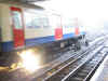
Such demonstrations of the power of electricity are a reminder
to those who might be tempted to disregard the safety rules just how powerful it can be.
|


 Fig 11: Shed receptacle on 1995 Tube Stock car.
 Fig 12: Overhead lead inserted on 1973 Tube Stock car
in Cockfosters Depot. Photo by Tube Troll
Fig 12: Overhead lead inserted on 1973 Tube Stock car
in Cockfosters Depot. Photo by Tube Troll