This website has been archived from TrainWeb.org/girr to TrainWeb.US/girr.
This website has been archived from TrainWeb.org/girr to TrainWeb.US/girr.
[ Home ] [ Up ] [ Previous Page ] [ Next Page ]
 19 Aug
01
19 Aug
01The Aristo ART-5474 Accessory Panel is a complete receiver intended to control accessories through the use of the A through E buttons on the Train Engineer transmitter. As the 5474 comes, it will control two turnouts, one constant load such as lights, and trigger two low current devices as the bell and whistle of many sound systems. Sometime in the future, there is also an ART-5475 receiver that is essentially identical, except that it is wired to control turnouts on all five outputs.
Note that the current (through 1999) version of the ART-5474 DOES NOT have a scanning receiver so that it will work with the 10 channel Train Engineer ONLY on frequency #1.
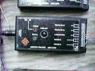 The unit is 4-1/4"" long by 2" wide by 7/8" high.
The power connector extends from one end and needs an additional 1-3/4"
of clearance to allow the connector to be removed. The screw type
output terminals accept stripped wires and are arranged on the other
end of the unit. A red LED on the top of the unit indicates power. A
green LED indicates that the receiver is receiving a command. A push
button allows the address code to be set.
The unit does have some operational and usage limitations which are not revealed in the instruction sheet that comes with the unit. The main one is that the power input and the A, B and C outputs are NOT ISOLATED from each other. This means that you CANNOT cross connect wires between these terminals on any individual 5474 or between 5474's. The D and E outputs are isolated with optical isolators and can be cross connected.
The output current capability of all of the outputs is limited. The turnout control outputs ("A" and "B") source a pulse of power but will only drive one turnout motor reliably. Some people have driven two, but then others have had their 5474's fail under these conditions.
The "C" output provides switched DC power and is rated at 200 mA, however my analysis shows that it is good for only 100 mA before the internal 10 ohm current limiting resistors will overheat. Also, neither output terminal is common to any other lead so that your load MUST float with respect to all other leads except the "D" and "E" outputs.
Outputs "D" and "E" are optically isolated bipolar transistors that will sink only about 10 mA. These outputs are polarity sensitive so that if they don't trigger your sound system, try reversing the leads.
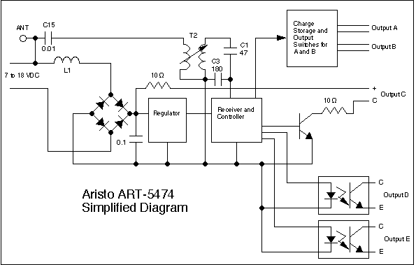
The antenna for the 5474 is internally connected to one of the power
leads. If you want to convert the 5474 to an external antenna then you
need to cut a trace on the printed wiring board and install a 3' or so
piece of wire to the hole marked "ANT." This hole is right next to the
power connector. Cut the trace leading from that hole to the input
inductor to isolate the antenna terminal from the DC power wires.
[ Top ]
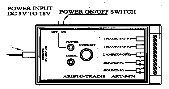
The labeling of the outputs on the 5474 is somewhat cryptic. The
diagram above shows the labels and what they connect to inside. The
table below is a summary of the outputs, current limits and signal
formats.
| Label | Output Code | Output Function | Output Labels | Output Format | Output Limits |
|---|---|---|---|---|---|
| Track-SW #1 |
|
Turnout Control | None | Capacitor Discharge Pulse, reverses polarity at each command | One LGB or Aristo turnout motor only |
| Track-SW #2 |
|
Turnout Control | None | Capacitor Discharge Pulse, reverses polarity at each command | One LGB or Aristo turnout motor only |
| Lamp (On/Off) |
|
Lighting or Smoke Control | "+" and "C" | Latched DC Power | About 100 mA max constant load, output voltage about 2 volts less than input voltage. "+" terminal provides constant voltage, "C" terminal is a sinking switch to the 5474 internal ground |
| Sound #1 |
|
Sound Control | "C" and "E" | Optically isolated pulse, output sinks current only, polarity sensitive | About 10 mA max, "C" terminal must be positive with respect to "E" terminal |
| Sound #2 |
|
Sound Control | "C" and "E" | Optically isolated pulse, output sinks current only, polarity sensitive | About 10 mA max, "C" terminal must be positive with respect to "E" terminal |
[ Top ]
I use five ART-5474's in my control panel for the GIRR and these provide adequate range and sensitivity. However, the one that I have moved between my Atlantic and RS-3 has provided inadequate range. I use it to control the bell and whistle, but at more about 10', control gets flaky. The one that I installed in my Pacific often didn't work at 1' range.
The units on the control panel use their power leads for their antennas. All five units are wired from a 12 volt DC power supply and there is about 10' of wire between the 5474's and the power supply. This wire acts as an antenna and I get reliable control anywhere on my layout, even in the garage on the other side of the house.
By experiment with the unit in the RS-3, I found that if I disconnected the antenna lead from the power lead and extended the antenna to 10', it worked pretty well. However dragging a 10' wire behind the engine isn't entirely practical.
I did find that on my particular unit, I could improve the sensitivity by tweaking on the RF transformer, T2, at the input to the unit. I DO NOT recommend that you try this unless you know what you are doing, because you could "tweak" the unit into complete nonfunctionality as well. Besides, it will probably void the warranty. Tweaking this particular unit helped quite a lot, but its still not good enough with an antenna short enough to package inside a locomotive.
Since it is pretty clear that the unit is not getting enough RF signal from the transmitter due to an inadequate antenna. Preamplifier circuits didn't seem to work, the unit is probably noise figure limited. Therefore the only way to improve the performance is to improve the signal that gets to it. Since operation at longer ranges is desired, the only way to improve the signal to the unit is to improve the antenna.
The 5474 just does not work inside an engine or tender due to the limited space for the antenna. The only way that I have been able to get it to work is to stretch the antenna out across the following cars. This is really inconvenient, but in some cases where the engine pulls a more or less dedicated consist, it can be done. It is also important to note that the antenna works MUCH better if it is higher from the ground. Even a few inches helps a lot. If you can get the wire as high as possible, it will work better for a given length.
[ Top ]
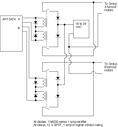
If you want to drive more than one turnout from the A and B outputs, you should use this simple circuit to allow an arbitrary amount of current switching capability limited only by the relays that you select. It takes two relays and 4 diodes per output to implement this circuit. You can get all the parts at Radio Shack.
[ Top ]
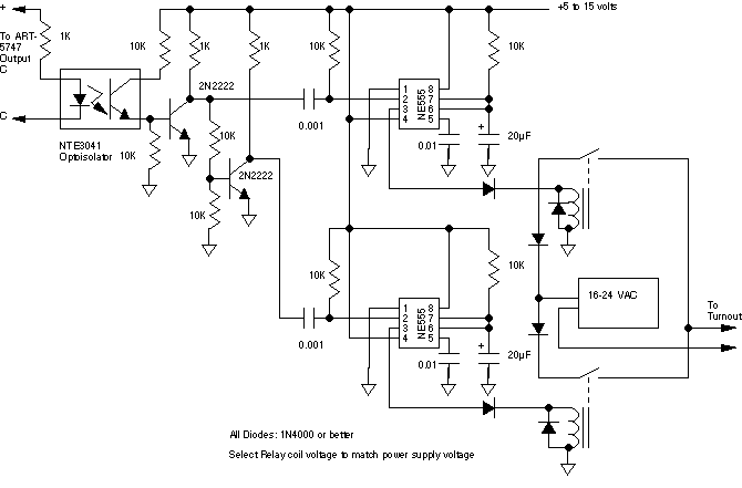
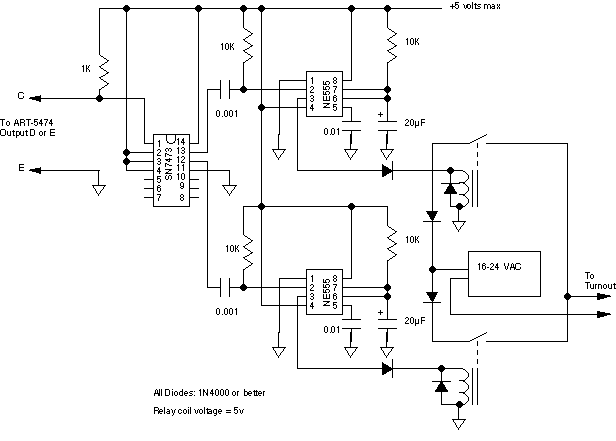
If you want to use all 5 outputs to drive turnouts, you have two options. You can use theART-5475 which is set up to drive turnouts on all five outputs, or you can build your own converter circuits for the 5474.
The using the 5474 and the following converter circuits, you can control up to 25 turnouts by using five 5474's linked to each of the 20 TE transmitter codes. The 5475 does not have the double touch control option, so using it with the "older" version of the TE transmitter allows only five turnouts to be controlled on each of the 20 TE transmitter codes. However, the "new" TE transmitter can control up to 50 turnouts (using ten 5475's).
The circuits below have not actually been tested in the form given. I use somewhat different and more complicated converter circuits in own control system as it has different requirements than controlling traditional turnout motors. However I think that they will work, or at least get very close to working.
These circuits work by conditioning the signals from the C, D and E outputs to trigger common integrated circuit timers to generate the output pulse, in this case about 200 mS. Since you need a pulse that changes polarity each time the output is commanded, you need two timers and two relays per output. There are probably slicker and less expensive ways to do this, but these circuits will present the fewest hassles in getting them working.
[ Top ]
The circuits below can be used to drive the solenoid air valves to remotely control Del Aire pneumatic turnout motors. In this case, one command causes the output to turn on and the next command causes it to turn off. The memory for the circuit is the 7473 JK flip flop.
The C output can be used directly to drive a solenoid, provided that the solenoid coil draws less than 100 mA. The A and B outputs need polarity conversion, isolation and latching. The D and E outputs need only to be latched.
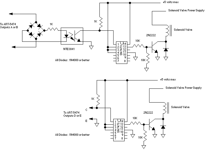
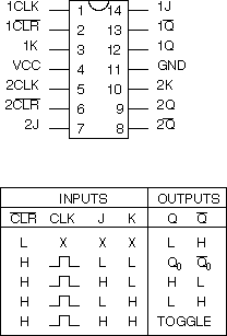 Note that the 7473 is a dual JK flip flop
and you can use the other half for another circuit. The circuit
diagrams got too busy to draw that way so here are the complete pinouts
for the 7473 and its truth table so that you can figure the proper
connections for a second circuit. The 7473 is being used in its most
basic mode, that of a toggle. Every time the CLK lead goes high, the
output will flip to the other state. This is described by the bottom
line of the truth table where J, K and CLR-not are held high all the
time.
[ Top ]
 The A and B outputs of
the 5474 can be used to drive twin coil switch machines such as Atlas
or the non-EPL LGB motors with the addition of just two diodes. Each
diode shorts out one coil for each polarity of the output of the 5474
so that only the other coil gets energized. Also, you only need to
route two wires to the motor instead of the more traditional three
wires.
You can also use the converter circuits shown above to drive this circuit to use all five outputs to drive twin coil machines although for twin coil machines the relay contact circuits can be simplified a little if twin coils are all that you intend to use.
If you use slow motion stall type machines, you will need to use separate relays with their coils wired like the switch machine coils in the figure to activate the machine. You also need to wire the machine to complete its own cycle. Refer to the manufacturer's instructions for information on how to wire the machine to work with a momentary contact. You can also use an Atlas Snap Relay to drive a stall motor.
[ Top ]
The ART-5474 A and B outputs can be used to trigger sound systems along with the D and E outputs but it requires some adaptive circuitry to make it work. If you want to trigger more than two effects, you can use an otherwise useless output to do it.
 This is the
low tech solution that used a small relay. Any kind will work, a reed
relay is preferred due to the low coil current draw. The resistor is
there to make up the difference between the relay's coil voltage and
the output pulse (usually about 20 volts) but most relays with a coil
voltage of 12 volts or greater will work well enough without it. Each
pulse of the ART-5475 will close the relay and trigger the sound
system. You can't "play" the sound like you can with the D and E
outputs, but you can trigger a pre-programmed sound.
 This is a
slightly different version of the same circuit. It uses a 4N33 (or
equivelent) optoisolator and suffers from the same operational
limitations as the relay version.
[ Top ]
I had some difficulty getting the code set to work when the transmitter was right next to the receiver where you might naturally hold it while setting the receiver. I had better luck holding the transmitter about 2' to 3' away.
In single touch mode you can use just one ART-5474 on each of the 20 transmitter channels, but you only have to press a button once to make something happen. In double touch mode, you can have 5 receivers on each of the 20 channels for a total of 100 receivers and 500 functions. However, you have to press two buttons to make something happen.
There is a difference in the output formats for the two modes. In single touch mode, outputs D and E will activate for as long as you hold down the button. In double touch mode, you will get an output pulse each time that you send a command. The impact of this depends on what you are controlling. If your sound system will play a sound for as long as it is triggered, it is possible to "play" the whistle in single touch mode but not in double touch mode.
In double touch mode, each 5474 receiver is addressed by the first button you press so that the first button selects one of 5 possible 5474's. The second button selects the output to activate on the selected 5474. If you press AB, then you will select the "B" output of the "A" receiver. In order to prevent the "B" receiver from hearing the second button of an AB command, ALL receivers that hear a command that isn't addressed to them will stop listening to anything for about 3 seconds. Unfortunately, this also applies to engine speed and direction commands, so if you've just commanded an engine, your 5474's will be deaf for 3 seconds. If you've just started and engine and need to throw a turnout right away, you're out of luck.
© 1997-2001 George Schreyer
Created Nov 3, 1997
Last Updated Aug 19, 2001