


This website has been archived from TrainWeb.org/girr to TrainWeb.US/girr.
 The Aristo 4-6-2
Pacific is a fine engine so I've found very little that needs fixing.
It pulls very well, it is quiet and smooth and mine tends to traverse
bad track (which I should fix) without derailing. However, I've found
some things that need attention and these are the subject of this
page.
The Aristo 4-6-2
Pacific is a fine engine so I've found very little that needs fixing.
It pulls very well, it is quiet and smooth and mine tends to traverse
bad track (which I should fix) without derailing. However, I've found
some things that need attention and these are the subject of this
page.
The Aristo Pacific is apparently modeled after the B&O President Class. The model matches the size, overall appearance and some of the detail locations of that class (pops, whistle and dynamo). Pacific's were predominantly passenger engines, however they could be pressed into freight service when necessary.
The model is nominally 1:29 scale and scales out pretty close. The model has fair detail and runs very smoothly and quietly.
 19 Jan 02
The Pacific is a heavy duty engine and can pull quite a load. See my Tractive Effort Tests page for comparative data of the Pacific vs. other common large scale locos. I use the Pacific primarily to pull a string of heavyweights. It will handle 5 cars with 6 wheel trucks on a 1.6% grade with 5' radius turns. The heavyweights drag so much on curves that the capability decreases to 4 cars when the grade has a 4' radius curve.
When overloaded, the Pacific will let you know. It doesn't slip gracefully. It stutters and hops around badly at the first sign of wheel slip. However, when the wheels are not slipping, it pulls smoothly and fairly quietly. The Pacific also tends to lug down under load just before it slips, much more so than most other large scale engines. I believe that this is due to the fact that it has only one motor instead of the more usual two. The motor is larger than most, but indications are that the larger motor does not produce the same tractive effort as locos with two smaller motors. This can be a problem if the engine is weighted to increase adhesion. The loco can load down so much that the motor starts to stall. This could cause serious overheating and eventual failure of the motor.
Early production Pacific's had gear drive to all six drivers. In later production, the gearing to the center driver has been removed so that the center drivers are driven only through the siderods. The driven axles are supported by ball bearings that are also used to transmit electrical power from the wheels.
There have also been at least two versions of the universal joint between the motor and the drive shaft. The earlier versions with a metal U-joint (visible between the firebox and the boiler) sometimes tended to make noise or transmit torque unevenly. My Pacific had a slight bind in the drive mechanism that occurred once per drive shaft turn. I thought that it was the U-joint, but after some investigation, it seemed to be coming from a drive shaft bearing. When I replaced the bottom cover of the engine, it went away so that I never did figure out the root cause of the problem.
[ Top ]The main weak point of the Pacific is its wheels. They are some kind of casting and they behave similarly to the wheels on the 0-4-0, in other words, they get dirty REAL fast. I don't know what the specific problem is but they just sweep up crud and power pickup gets flaky.
One of our compatriots from New Zealand, Grant Alexander, has found that chrome plating of the wheels makes a world of difference. Aristo has changed the wheel material for the 0-4-0 which made an astounding improvement in power pickup reliability. I hope that someday Aristo will make the Pacific's wheels in the same material.
In the meantime, you can wire the tender across to the loco to add 8 more wheels of power pickup. This helps a lot, but the tender wheels are made of the same stuff and they get cruddy too.
The other problem with the drive wheels is that the screws that hold them on get loose and fall out. You may not notice it for awhile as the siderods tend to hold a loose wheel in place. The axles have drift pins installed that pick up slots on the backs of the drivers so that even if a wheel is wobbling on its shaft, it will still be driven. The Pacific tends to wobble or waddle under load somewhat, but when even one wheel gets even a little loose, it'll start to wobble much more. Pay attention to its little dance and if you see it start to get worse, stop then and there and tighten the driver screws before you actually loose one of them.
It is a good idea to use a little purple LocTite 222 (the type rated for SET SCREWS) to hold the screws in place as simple torque and lock washers don't seem to do the job.
[ Top ]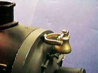 The Pacific has fair detail, but its not up to the
detail of newer large scale locos. Further, some of the details look
out of place, like the bell on some versions. The ATSF version mounts
the bell harp on top of the boiler, a prototypical location, but it
sticks up way too high and looks odd. Besides, the damn thing keeps
getting broken off. I remounted it on the smokebox cover, also a
prototypical location for some road names. Pull the harp from the
boiler then fill, file and paint the old mounting location. Then drill
a 1/8" hole in the smoke box cover. There are three holes there
already, drill out the center one. Cut off the base of the harp and set
the harp in the new hole with a drop of superglue.
The Pacific has fair detail, but its not up to the
detail of newer large scale locos. Further, some of the details look
out of place, like the bell on some versions. The ATSF version mounts
the bell harp on top of the boiler, a prototypical location, but it
sticks up way too high and looks odd. Besides, the damn thing keeps
getting broken off. I remounted it on the smokebox cover, also a
prototypical location for some road names. Pull the harp from the
boiler then fill, file and paint the old mounting location. Then drill
a 1/8" hole in the smoke box cover. There are three holes there
already, drill out the center one. Cut off the base of the harp and set
the harp in the new hole with a drop of superglue.
The pilot can be removed so that a front coupler can be attached to the leading truck to allow double headed operation. The coupler mount is standard and an Aristo or Kadee #831 will go right on.
[ Top ]The smoke system is run from a fan that pressurizes the smoke unit. The smoke unit itself sits on the front deck. The smoke that leaves the unit is conducted up a brass tube to the smoke stack. There are two plastic tubes leading down from the stack that conduct a part of the smoke back down to the cylinders to simulate leaking steam.
The smoke unit is controlled by a switch on the front deck. Pulling the switch forward activates the smoke unit. Pressing it back disconnects the smoke unit.
The fan itself is run from a low voltage motor in series with the smoke unit. There are two dual diode stacks in parallel with the motor to limit the voltage that the motor can see. Unlike other Aristo fans, this one can run in either direction and still pressurize the smoke unit.
Smoke fluid must be added to the fluid tub on the pilot deck. Pouring it down the stack usually will not work as it has to get down the very small brass tube. The top cover of the fluid tub must be replaced or the smoke will just pour out of the tub.
The smoke unit can be removed quite easily. First, pull up on the ENTIRE smoke stack assembly until it moves upward about 3/8". Do not try to pull it all the way off. This lifts the brass tube out of the top of the smoke unit. Then pull the smoke unit itself out forward. If it does not come right out, then pull up on the stack assembly a little so that the brass tube clears the top of the smoke unit. This is all easier to see if you remove the smokebox front cover. Reinstall the smoke unit the same way, when the unit has seated properly, press the smoke stack assembly back down to lock the smoke generator in place.
[ Top ]The Pacific Tender comes with a sound system installed. This system has been much derided, but under the right conditions it isn't too bad.
The system chuffs fairly well and rings a sort of a bell sound at low speed. There is no whistle. However, the sound system relies on the Aristo PWC system to work. Without PWC, the sound system doesn't get enough voltage off the track to work properly and it howls, growls, and screeches terribly at low speed. With PWC, it may make awful sounds but only at very slow speed.
In either case, the sound can be improved by opening the tender and installing a RECHARGEABLE 9 volt battery in the clip provided. The upside is that the sound system will operate at low speed and sound OK. The downside is that the engine can be stopped with the chuff blowing constantly as is common on a Bachmann Big Hauler. I use PWC so I don't use the battery and the sound shuts off when the track power goes away completely.
The chuff trigger is a Hall effect device mounted above a tender axle. A doughnut shaped magnet rides on a rubber roller on the axle. The Hall effect device is mounted next to the magnet. If the chuff isn't working right, make sure that the rubber roller is clean and that the Hall effect device is RIGHT NEXT to the magnet. Even when its working, the chuff rate is about 1/3 of the prototypical rate of 4 chuffs/turn.
After the rubber roller gets old and hardens up some it doesn't provide enough friction to turn the magnet reliably. After much fussing and fiddling, I finally tried to renew the roller surface with a coating of contact cement, AND IT WORKED! To apply the cement, pull the wheelset with the roller from the truck by flexing the truck sideframe slightly and then paint a layer of contact cement on the roller. Rubber cement would probably work too. Let it dry for about an hour and reinstall the wheelset. I do not know how long this patch will last, but even if it fails after awhile, it would be easy enough to do it again.
There is an adjustment on the sound board for bell sound. Diddling on it can make the sound a little better or more likely much worse and getting the best (not good but best) sound requires a fairly touchy adjustment of this control. You can try to adjust it, but don't expect miracles.
[ Top ]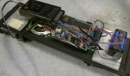 I finally got tired enough
of the stock sound system to spend the $110 or so to upgrade the sound
system to Aristo's new ART-29341 digital sound system. This system
isn't really new, its a version of the PH hobbies S3005S that's been
around for several years. The system has a basic chuff, bell and
whistle sounds with blowdown and compressor sounds while the engine is
standing. The board has been modified to fit the mounting posts of the
Pacific tender and to deal with the Hall device chuff sensor. The
system is mostly a plug in installation, no soldering is required.
I finally got tired enough
of the stock sound system to spend the $110 or so to upgrade the sound
system to Aristo's new ART-29341 digital sound system. This system
isn't really new, its a version of the PH hobbies S3005S that's been
around for several years. The system has a basic chuff, bell and
whistle sounds with blowdown and compressor sounds while the engine is
standing. The board has been modified to fit the mounting posts of the
Pacific tender and to deal with the Hall device chuff sensor. The
system is mostly a plug in installation, no soldering is required.
I installed the device per Aristo's typically brief instructions and I did have some minor difficulties, mostly due to wires that were too short.
I mounted the 5474 on the back of the speaker with another piece of foam tape. The lugs were clipped off and the power leads and the leads were soldered to the circuit board where the leads to the front truck terminate. I also added a pair of 100 microhenry inductors to isolate the power leads from the track. An antenna wire extends rearward to connect to the following car.
Initial results with the 5474 were not so good. While it does trigger the bell and whistle, the range is not adequate. Sometimes it doesn't work standing right next to the engine. I tested this particular 5474 on the bench and I could trigger the whistle from 50' away which as far as I could hear it when the unit was inside the garage and I was in the backyard. However, when installed in the tender and sitting on the track it doesn't work nearly as well.
There isn't enough room for an adequate antenna for the 5474 inside the tender. No amount of rearrangement of an antenna wire would work. I stretched a 3' piece of wire back across the following car (a heavyweight) and it worked much better. I also found that if the wire was stretched under the car, it didn't work nearly as well if the wire was taped to the car roof. I eventually routed the wire just under the roof and connected it to the tender with an set of DB-25 contact pins (see my Connector Tips page for details on the connector. Just as a precaution, I also routed the end of the wire back down the other end of the car and installed a connector there too in case I need to further extend the wire across the NEXT car.
With the antenna wire extending just under the roof of the car, I can usually trigger the sound system from about 50' although it still doesn't work every time.
 The battery charging of the
digital sound system is similar to other sound systems manufactured by
PH Hobbies. The system will charge better from PWC than from pure DC.
These curves show the battery voltage as a function of average input
voltage. With PWC, the battery will start to charge at lower average
input voltage than with DC. This system is essentially identical to the
old one in my Atlantic and it has never needed a charge since the day
that I installed it. I expect that the Pacific system will work the
same way.
The battery charging of the
digital sound system is similar to other sound systems manufactured by
PH Hobbies. The system will charge better from PWC than from pure DC.
These curves show the battery voltage as a function of average input
voltage. With PWC, the battery will start to charge at lower average
input voltage than with DC. This system is essentially identical to the
old one in my Atlantic and it has never needed a charge since the day
that I installed it. I expect that the Pacific system will work the
same way.
 This is the schematic of the Pacific as
built by Aristo. Fortunately all the necessary wiring is readily
accessible with the cab and boiler removed. The cab comes off with 4
screws. The boiler comes off with five more, four underneath and one on
top at the joint between the boiler and the smokebox. Refer to Aristo's
Exploded Diagrams for details on the locations
of these screws. The two brass handrails can be unclipped from the
front two stanchions on each side of the smokebox and the cab and
boiler can be lifted off.
This is the schematic of the Pacific as
built by Aristo. Fortunately all the necessary wiring is readily
accessible with the cab and boiler removed. The cab comes off with 4
screws. The boiler comes off with five more, four underneath and one on
top at the joint between the boiler and the smokebox. Refer to Aristo's
Exploded Diagrams for details on the locations
of these screws. The two brass handrails can be unclipped from the
front two stanchions on each side of the smokebox and the cab and
boiler can be lifted off.
Battery power users will note that the inside of the boiler has a huge amount of USABLE volume to allow battery installation. The interior clear space is fully 13" long and slightly over half round at 2.5" in diameter.
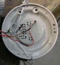
 This is a view of the firebox area of
the Pacific. Track power is brought up into the shell and attached to
two lugs seen at the right of the photo. From here, power is routed
back to the two switches in the cab floor. One controls the cab lights,
firebox light and motor. The other controls the headlight and markers.
Smoke unit power is wired from underneath the boiler directly to the
smoke unit. I ended up removing all this wiring and abandoning the
switches altogether. The cab light, firebox light and motor are all
wired separately to the decoder. The only original connections left on
the power lugs are the wires coming up from under the engine that
connect to the power pickups on the drivers and the trailing truck. The
only new connection to these lugs goes to the power input of the
decoder and to the rectifier used to power the smoke unit.
This is a view of the firebox area of
the Pacific. Track power is brought up into the shell and attached to
two lugs seen at the right of the photo. From here, power is routed
back to the two switches in the cab floor. One controls the cab lights,
firebox light and motor. The other controls the headlight and markers.
Smoke unit power is wired from underneath the boiler directly to the
smoke unit. I ended up removing all this wiring and abandoning the
switches altogether. The cab light, firebox light and motor are all
wired separately to the decoder. The only original connections left on
the power lugs are the wires coming up from under the engine that
connect to the power pickups on the drivers and the trailing truck. The
only new connection to these lugs goes to the power input of the
decoder and to the rectifier used to power the smoke unit.
I used a Lenz LE230 back-emf decoder in the Pacific. I chose this decoder because it was the only high current back-emf decoder that I could find and it had received good performance reports from other users. Zimo also makes a good back-emf decoder, but the one that I had on order was backordered for almost 4 months and I was tired of waiting for it. The Pacific really needs the motor speed control that back-emf provides because its speed tends to be quite sensitive to load. Mine will lug down on upgrades and run away on downgrades. Back-emf can keep these speed variations under better control. The LE230 is rated at 2.5 amps continuous output. The Pacific draws about 1.6 amps while slipping so the LE230 ought to be able to handle it.
DCC installation in the Pacific is a pretty straightforward task, except for the smoke unit. The only high current (500 mA) function output of the LE230 is F1 which I prefer to use for the sound system bell instead. None of the other function outputs have the current capability to run the smoke unit directly (400 mA cold, 250 mA hot). I usually prefer to leave my smoke units connected to the track so that they are controlled by the regular smoke switch instead of the decoder and therefore don't add load to the decoder. Also, if the smoke function gets turned on by accident when it is dry, I don't toast the smoke units. However, the Pacific smoke unit uses a fan to force air out of the smoke unit and the fan motor will not run on DCC track power which is AC. Therefore I added a bridge rectifier to the smoke unit to create the necessary DC power and further I wired it from a relay (visible in the next photo) so that it could be run from a low current function output. The switch on the pilot deck will still turn it off. Unlike other Aristo smoke system fans, this one operates properly with the fan turning in either direction.
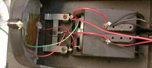
 This photo shows the top of the fan
assembly. One power wire is routed up to the left side of the circuit
board, the other is routed to part of the smoke switch underneath. Both
wires must be removed and insulated. They will not be used in the DCC
installation. New wires are soldered to these points and brought up to
the bridge rectifier and relay. The relay and rectifier are glued to
the engine weights with GOOP. Track power for the smoke unit is wired
from the main power lugs in the firebox.
This photo shows the top of the fan
assembly. One power wire is routed up to the left side of the circuit
board, the other is routed to part of the smoke switch underneath. Both
wires must be removed and insulated. They will not be used in the DCC
installation. New wires are soldered to these points and brought up to
the bridge rectifier and relay. The relay and rectifier are glued to
the engine weights with GOOP. Track power for the smoke unit is wired
from the main power lugs in the firebox.
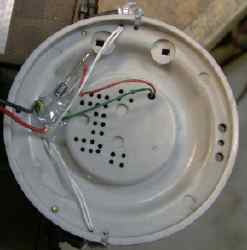 The
stock headlight wiring is pretty straightforward. This is the stock
wiring. Two wires coming from the switches in the back bring power to
the markers and to the headlight. The headlight is powered through a
diode to make it directional.
The
stock headlight wiring is pretty straightforward. This is the stock
wiring. Two wires coming from the switches in the back bring power to
the markers and to the headlight. The headlight is powered through a
diode to make it directional.
 Headlight and marker wiring
modifications are easy. The headlight wires are removed from their
previous connections and extended with new wire. The original wires run
only the markers and can either be left connected to the original
switch or wired to a decoder function. The headlight is connected
directly to the decoder as shown in the decoder instructions. If you
want to dim the headlight in when running in reverse, cross connect the
forward and reverse headlight decoder function connections with a 150
to 220 ohm resistor.
Headlight and marker wiring
modifications are easy. The headlight wires are removed from their
previous connections and extended with new wire. The original wires run
only the markers and can either be left connected to the original
switch or wired to a decoder function. The headlight is connected
directly to the decoder as shown in the decoder instructions. If you
want to dim the headlight in when running in reverse, cross connect the
forward and reverse headlight decoder function connections with a 150
to 220 ohm resistor.
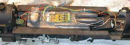 This is the Pacific after
the DCC installation was completed. Virtually all the original wiring
is gone and replaced with wiring to or from the DCC decoder.
This is the Pacific after
the DCC installation was completed. Virtually all the original wiring
is gone and replaced with wiring to or from the DCC decoder.
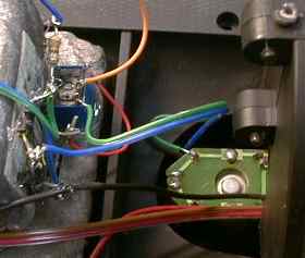
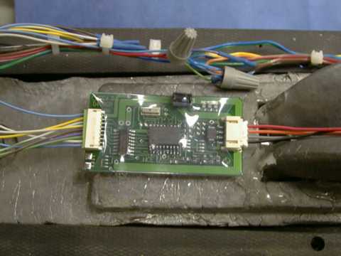
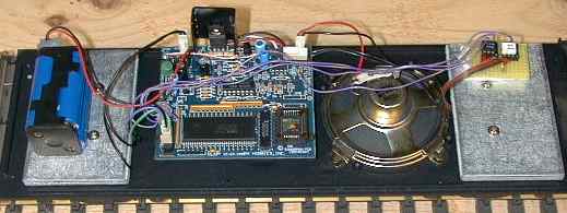 The tender
houses the Aristo Digital Sound system. The bell and whistle used to be
controlled by an ART-5474 accessory receiver, but now they are
controlled through optoisolators from the DCC decoder. I choose to
mount the generic optoisolators in the tender on a small circuit board
seen in the upper right of the photo. Connection to the loco is made
through a 3 pin Molex connector carrying the F1 and F2 function leads
and the blue decoder wire.
The tender
houses the Aristo Digital Sound system. The bell and whistle used to be
controlled by an ART-5474 accessory receiver, but now they are
controlled through optoisolators from the DCC decoder. I choose to
mount the generic optoisolators in the tender on a small circuit board
seen in the upper right of the photo. Connection to the loco is made
through a 3 pin Molex connector carrying the F1 and F2 function leads
and the blue decoder wire.
I eventually destroyed the stock speaker while removing the 5474 which has been foam taped to the back of the speaker (the rear pole piece came off with the 5474) so I have replaced it. I used a generic TV replacement speaker. Later I found that a Radio Shack 40-252 speaker would fit as well.
Some of the DCC signal leaks into the PH sound board causing a high pitched buzz. It isn't too loud if the batteries are well conditioned. However, dead batteries or batteries with poor connections in the holder will allow a fairly loud buzz. Cleaning the battery ends and the holder contacts may reduce the AC impedance of the battery stack. I found that a 10 uF capacitor soldered across the battery terminals on the circuit board also helped to attenuate the noise.
There will still be some residual noise that couples directly to the board from the rails. The PH board has a lot of audio gain and just putting a finger near the volume control will couple in more noise. There probably isn't much that can be done with the residual noise.
When running on constant DCC track voltage, the regulator IC on the PH sound board will get too hot and eventually thermally shut down to protect itself. If your batteries are any good, you may not notice it as the sound system will continue to run on the batteries until the regulator cools enough to turn itself back on. This will continue to happen unnoticed while the regulator is getting beat up. A better plan is to add a heat sink to the regulator so that it doesn't heat so much.
It all worked pretty well. The decoder F5 (firebox) and F6 (smoke) functions did not initially work. This turned out to be an incompatibility between the Lenz LE230 decoder and the Digitrax Chief command station. I eventually sent the Chief back to Digitrax for anther problem (it literally burned up) and when it came back, F5 and F6 began to work.
The back-emf feature of the decoder interacted with the mechanism somewhat. This Pacific had a slight bind in the drive line that occurred once per driveline turn. It was so slight that I never noticed it when running track power. However, when back-emf is enabled on the decoder, it does have an effect. The back-emf sensor in the decoder tries to keep the motor speed constant but it responds a little slowly. When the driveline binds, the decoder senses it and tries to correct by adding a little more power. However, by the time that the decoder corrects, the bind is gone and the power is not necessary. The locomotive then surges just a little. This only happens when the engine is running light. When loaded, it does not seem to be a problem. I worked over the driveline a little this characteristic improved, but it still needs a little more work.
The Pacific is a little under motored. It has a large motor, but there is only one and it doesn't have quite enough torque. It tends to lug down more than most locos under heavy load. I was hoping that back-emf decoder would help by keeping the average speed up and down the grades more constant. Since the motor was lugging anyway on the upgrade, the decoder could not help. It helped some on the downgrade. It seems that the back-emf implementation in this decoder senses a short period running average of motor speed. When running down a long downgrade, the back-emf system sees no short term changes and eventually allows the engine speed to increase.
Under steady heavy loads, this decoder gets warm but not hot. It doesn't make nearly as much hammering noise as the Digitrax decoders at slow speed. However, the feature set of the LE230 is somewhat limited. It does not operate in 128 speed step mode and has no special effects on any functions. The decoder converts to analog gracefully although none of the decoder functions operate when analog converted. I cannot program the CV's in this decoder using OPS mode on the main line with my Digitrax Chief. I have to do all programming in PAGE mode on the programming track.
One of my kids dropped the Pacific and broke a bunch of parts. Since it was out of service anyway, I removed the LE230 and reinstalled it in a Bachmann Climax. While I was waiting for the parts (Aristo was moving their facility and their parts department was out of service also) I patched it back together and rewired it for track power. I found that it actually ran stronger under straight track power than with the LE230. It didn't tend to lug down as much. I then suspected that the Pacific might be just a little too much of a load for an LE230 as the decoder was probably going into current limiting.
I also received a repaired and upgraded DG-580L back from Digitrax so I stuck it in the open engine to see how it worked. It didn't work too well. Due to some added heatsinking on the decoder, it didn't burn right up, but it didn't put out enough current to run the Pacific either. The engine stalled badly in spots where it worked with either straight track power or the LE230.
 After 15 months on backorder, a Zimo
MX65S/N finally showed up. This is a slightly larger (3 amp) back-emf
decoder than the LE230. The Zimo is a really fine unit. It is well heat
sunk so it will probably stand up to abuse well, unlike the Digitrax
units. Its back-emf control is just as effective as the Lenz decoder
and the back-emf effect is programmable from a hard speed lock to a
weak speed lock.
After 15 months on backorder, a Zimo
MX65S/N finally showed up. This is a slightly larger (3 amp) back-emf
decoder than the LE230. The Zimo is a really fine unit. It is well heat
sunk so it will probably stand up to abuse well, unlike the Digitrax
units. Its back-emf control is just as effective as the Lenz decoder
and the back-emf effect is programmable from a hard speed lock to a
weak speed lock.
As delivered, the back-emf feature interacted more strongly with the gearing bind than the Lenz LE230 did. However, a little messing with the programming of the back-emf (CV58) and I found that with the CV set to about 75% I could get a strong enough interaction AND eliminate the binding at low speeds. The Zimo unit seemed to be able to drive the Pacific under load better than the Lenz decoder, it doesn't lug as much as it used to under heavy load. However, this could also be due to the NCE PB110 booster that I am using now. The PB110's output voltage doesn't sag nearly as much as the Digitrax Chief's booster.
The Zimo MX65S/N analog converts well with either DC or PWC on the track. The reversing headlight operates properly, but none of the other functions operate.
 I wired the Zimo
the same as the Lenz with the same functions. However, for some reason,
Zimo starts counting functions at 1 while everybody else starts at 0.
Therefore, the Zimo function numbering on the decoder is offset by one
from the numbering on the DCC throttle. Even though Zimo calls the
headlight function 1, it still responds to the F0 controls on the
throttle. All other functions are offset the same way. The numbering in
the schematic uses Zimo's convention.
I wired the Zimo
the same as the Lenz with the same functions. However, for some reason,
Zimo starts counting functions at 1 while everybody else starts at 0.
Therefore, the Zimo function numbering on the decoder is offset by one
from the numbering on the DCC throttle. Even though Zimo calls the
headlight function 1, it still responds to the F0 controls on the
throttle. All other functions are offset the same way. The numbering in
the schematic uses Zimo's convention.
After running the engine for quite a while with the Zimo decoder I concluded that it still didn't work as well as when it was running from straight track power using a Train Engineer as a power source. I surmised that even the Zimo was current limiting. When then engine lugged down and started to draw more motor current it would cause the output voltage of the decoder to drop off and the motor would then lug worse. The decoder back EMF control would then tried to boost the motor power by going to full pulse width but there just wasn't enough current available to cause the motor to pull out of the stall. Both the motor and the decoder would then overheat. The Train Engineer has enough current capability to hold up its output voltage so that it could drive enough current into the motor to keep its torque up and to prevent the motor from slipping into a stall.
I considered reconverting the loco back to analog control, but I decided to give it one more shot using a new NCE D408SR decoder. I have had very good results with an earlier version of this decoder in a pair of RS-3's. The D408SR is rated at 4 amps average, the Zimo at 3 amps and the Lenz LE230 at 2.5 amps. Maybe the extra amp would be enough to keep the motor from sliding down the wrong side of the torque curve.
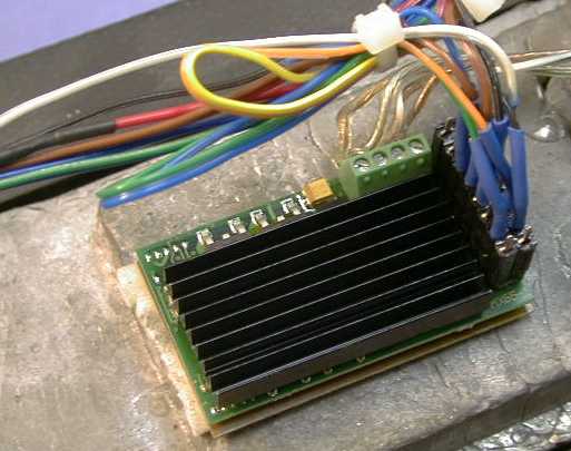
 The D408SR did indeed work very
well, maybe better than the Train Engineer did. The engine still slows
somewhat at the worst spots on the grades, but it pulls through. More
important after extended running, the motor and decoder are only warm,
not hot like with the smaller decoders.
The D408SR did indeed work very
well, maybe better than the Train Engineer did. The engine still slows
somewhat at the worst spots on the grades, but it pulls through. More
important after extended running, the motor and decoder are only warm,
not hot like with the smaller decoders.
The D408SR does not have back EMF motor control. This is good and bad. The good part is that the decoder doesn't try to ram more power into the motor when it lugs. The bad part is that the engine tries to run away downgrade. However, by setting the Vmax CV on the decoder to limit the maximum running speed, I can limit the downgrade speed to safe values and still have enough power to pull the grades going up.
The schematic of the installation is similar to the one used in the Zimo configuration, except the 150 ohm resistor on the reversing headlight is not needed. The D408SR can dim its own headlight. The smoke unit is wired to the output normally used for the reversing headlight. This output has been remapped so that it is disconnected from the headlight function and operates in both directions.
Aristo Craft has posted exploded diagrams of the Pacific at Exploded Diagrams. They are .PDF files so that you need Adobe Acrobat Reader to read them, but there is also a link on the exploded diagrams page to get a free copy of Acrobat Reader. These diagrams are extremely useful and I would recommend that you download the diagram, print a hard copy and study it before you take your Pacific apart for the first time.
The cab and boiler can be easily removed to expose most of the wiring. Four screws under the frame release the cab. Four more screws under the walkways and a fifth screws on the top at the joint between the boiler and the smokebox release the boiler. You also have to unclip the handrails from four clips on the smokebox.
The drive train is accessed by removing eight screws on the bottom cover. The gearing on the front axle is not directly accessible as the gear assembly is inside its own gearbox. The gearbox can be removed and disassembled to lubricate or adjust the quartering of the drivers.
The motor and U-joint can be removed by removing the rear truck and then removing three screws under the firebox that hold on the bottom motor cover.
The fan assembly is especially difficult to remove. It looks like much of the engine would have to be taken apart to remove it.