This website has been archived from TrainWeb.org/girr to TrainWeb.US/girr.
This website has been archived from TrainWeb.org/girr to TrainWeb.US/girr.
PWC stands for Pulse Width Control. This is a system that Aristo has developed to enhance the performance of some features of DC powered model trains, particularly smoke and lights.
"Pulse" power has been used for quite awhile in HO power packs, but there is a significant difference between conventional pulse power and PWC. Conventional pulse power uses fairly long, low repetition rate pulses which produce the pronounced hum often experienced with these systems. PWC differs in that its pulses are short and at a high repetition rate. This difference can be used to provide some side benefits.
The motors in DC powered trains have internal inductance due to their windings. One property of an inductor is that it doesn't allow rapid changes in current flow. Therefore when you apply a short pulse to a motor, the actual current that flows will be smaller that you would expect. However, resistive loads such as lights and smoke units can accept the full power of the pulse. The motors reject the leading edge of the pulses, when the pulse is short the whole pulse gets rejected. As the pulse widens, only the leading edge of the pulse is rejected and the remaining part of the pulse can flow in the motor.
The real advantage of PWC is that smoke units and lighting will come on with more intensity at low locomotive speeds. At higher speeds, the difference between PWC and pure DC becomes insignificant.
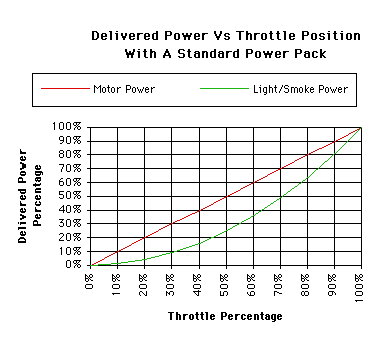 DC motors tend to be constant current
devices, that is the current drawn by the motor is more determined by
the load on the motor than by the applied voltage. Therefore the power delivered to the motor and hence its speed are nearly directly proportional to the applied voltage.
Resistive loads such as lights and smoke react differently. Their power
is proportional to the square of the applied voltage. The graph shows
that the power delivered to lights and smoke falls off faster with
reduced throttle than does the power to the motors. With PWC, the
lights and smoke draw full power when the pulse is on so that the
delivered power is again proportional to throttle, somewhat like a
motor. Add this to the delay that the real motors get due to their
inductance, and the power delivered to lights and smoke is actually
higher than the power delivered to the motors at low throttle.
In the case of incandescent lamps, the effect can be even more pronounced. At low filament temperatures, the resistance of the filament is lower than when the lamp is full bright. Therefore it draws even more current until it heats up. This causes a lamp to brighten up even more when pulsed at less than 100% duty factor.
The PWC pulses are generated by electronic circuits inside the power packs or Train Engineer receivers. Because the current is switched either fully on or off, the PWC systems can handle more current without heating up as much as truly linear power packs.
I use PWC to advantage in getting some accessory electronic circuits like lighting, smoke and sound system battery charging to operate at nearly full function at very low engine speeds. See Shay Tips or Heavyweight Tips for examples of how to take good advantage of PWC. These circuits store energy supplied during the short full voltage pulses to allow the circuits to continue to run properly between the pulses.
PWC can enhance the capability of sound systems to charge their undersized batteries at slow engine speeds. My sound systems (PH and Sierra) typically do not need offline battery charging even with extended slow speed running. The RS-3 sound system can be made to charge off the PWC pulses as well, see RS-3 Tips for more details. With linear power, I find that the track voltage must be about 10 volts before the NiCad battery gets significant charge. With PWC, the battery voltage on the PH sound system in my Atlantic starts to increase when the average track voltage is about 2 volts, just enough to get the engine to start to move.
There have been any number of claims made that PWC burns up motors. "Coreless" motors are the most often claimed to be incompatible with PWC. While I can't say that its never happened at all, it certainly has never happened to me. I've yet to burn up a motor in any LGB, Aristo or Bachmann loco while using PWC.
One known incompatibility is between PWC and Lionel Railsounds. It is a fact that running Railsounds on PWC will burn up the Railsounds unit in a very short time.
Some LGB sound systems do not respond well to PWC. They get fooled by the peak voltage of the pulses and run up to full speed right away. There is no known workaround for this problem. If you use LGB digital sound, use the Linear setting. This produces the pure DC that LGB recommends through filtering of the output pulse train. The TE still makes PWC internally, but by the time the power gets to the output terminals, it's pure DC with very little ripple or noise.
Aristo PWC operates somewhat differently in different Aristo power packs. I have characterized two, the ART-5400 and the ART-5471 Train Engineer. I understand that the ART-5490 mini-receiver operates the same as the 5471, but I have not confirmed this.
I've observed the outputs of these two packs on an oscilloscope and made the drawings found below to what happens in each pack. I tried to get photos, but they didn't look too good. There is quite a bit of jitter, overshoot and ringing in the pulses so actual photos are more confusing than necessary. None of this chaff has any real impact on how PWC works. Instead of showing photos, I have made simplified drawings of the outputs to show the major impact of what is going on.
[ Top ]
Aristo starter sets come with a small power pack, the ART-5400. This pack is rated at 1.8 amp which is considerably more powerful than the typical starter set pack. The pulse repetition frequency is about 7 kHz so that the pulses can be heard as an annoying high pitched whine under some conditions.
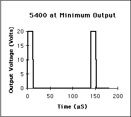 At the minimum setting of the 5400, it outputs a
string of short pulses at about 12 microsecond width and 140
microsecond period. This low average energy is not enough to get motors
moving but lights will respond.
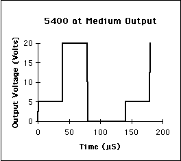 At a medium power setting, a pedestal is added in
front of the high voltage pulse and the pulse itself is widened. The
pedestal is supplying most of the power that gets to the motor and the
higher voltage pulse is mostly driving the lights. As the high voltage
pulses get longer, some of their energy is getting to the motors as
well.
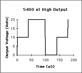 At a setting somewhat below maximum output, the high
voltage pulse is considerably widened and the pedestal voltage is
increased. Now the pulse is so long that much of it is getting to the
motors which reject only the leading edges of the pulses. At full
output, the pulses merge together completely and the output becomes
nearly pure DC current.
[ Top ]
The Train Engineer receiver works differently than the 5400. There is no pedestal before the main pulse. This is pulse width modulation in the normal sense. Also, the pulse repetition frequency is higher, about 25 kHz, so that you can't hear it under any conditions.
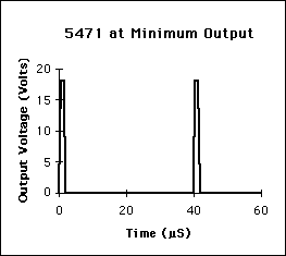 At minimum output the 5471 outputs a very short
pulse. The drawing shows it as nearly a square pulse, but it really
looks more like a half sinusoid with about a 1 microsecond period at
the half power points. I found it hard to make the receiver generate
this wave form while increasing the output from zero. To get this
output, I usually had to go up in power a little then back down.
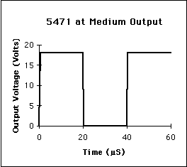 At medium output, the pulse simply widens as the
power output is increased. The voltage of the pulse remains constant,
in my case about 18 volts.
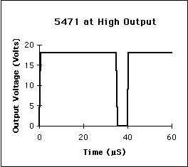 At nearly full output, the pulses have widened so
that they nearly fill in. When the output finally tops out, the pulses
fill in completely and the 5471 outputs DC power at 18 volts. The peak
pulse voltage depends on the input voltage to the 5471, if you apply
higher DC in, you'll get higher DC out.
The 5471 has a linear mode of operation. In this mode, it works just like any pure DC power supply with only minimal ripple on the output. The DC voltage will change from zero to 18 volts or so depending on the speed setting. The linear mode is created internally by the same PWM modulator that makes the PWC signal. However, the output pulses are filtered internally to integrate the pulse waveform back to its average component. This is why the TE can control a high current DC output without heating excessively where other DC power packs may get quite hot.
In either mode, when you reach maximum output and keep pressing the Fast button, the receiver will record those steps but not do anything. When you want to go slower again, you have to tick down through those steps before anything happens at the output. In the later versions of the TE (year 2000 version), this problem has been fixed.
[ Top ]
Now that you know what PWC is, there are some interesting things that you can do to take advantage of its characteristics. The most obvious thing is to improve the performance of lights and smoke beyond what you get with PWC by itself. Specific examples of some of these circuits are shown in RS-3 Tips, Shay Tips, Big Hauler Tips, and Heavyweight Tips. The biggest improvement in smoke and light performance provided by these circuits will be at low to medium speeds.
The trick used here is that the full voltage pulses can be used to charge a storage capacitor that then dribbles out charge to regulator circuit between the pulses so that the regulator can maintain its regulated output voltage constantly. Just as soon as the first narrow pulses are generated by the Train Engineer, but before enough energy is available to run the locomotive motors, accessory lighting and smoke circuits can be running at or near full intensity. You get full brightness lighting and full smoke while the locomotive is literally crawling. This works MUCH better than even the conventional "constant intensity" lighting that is commonly used in some locomotives.
There is a hidden dark side to this method, although it doesn't have to be a problem. An LGB 5 volt smoke unit draws about 200 mA of average current. The capacitor will have to supply that 200 mA all the time so that during the short time that the pulses are available to charge it, it'll have to charge at much higher current. If the pulse duty factor is 10% (duty factor is the ratio of pulse width to the pulse period), the capacitor charging current will be 2 Amp. With shorter pulses, the current can be higher. Your power pack has to be able to provide high peak currents or the circuit won't work as well as it could or the power pack may even overload. A typical 10 amp power supply driving the Train Engineer receiver is adequate to run several of these circuits along with your locomotive motors.
The 5400 pack will marginally run an RS-3 with the smoke running, but if a capacitor is installed as shown in RS-3 Tips, the pack to go into overload due to the much higher peak currents while the capacitor charges.
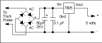 This is the circuit that you should use if
you are driving 5 volt loads such as an LGB 65853 smoke unit. It uses a
commonly available 5 volt regulator integrated circuit called a 7805
(Radio Shack 276-1770). The 7805 accepts any input voltage between
about 7 and 35 volts and provides a constant 5 volt output. There are
other regulators in this family that provide different fixed output
voltages. There are also negative polarity versions. The 7805 is called
a linear regulator as it acts as a really fast variable resistor to
compensate for changes in the input voltage. Since the input current
and output current of the regulator are nearly the same, the excess
energy of the higher input voltage is dissipated as heat. The
integrated circuit is both short circuit and thermal overload protected
so it is really hard to damage it. However, reversing the input
polarity will blow it up.
A circuit called a "bridge rectifier" (the 4 diodes) is used to keep the polarity correct. The bridge rectifier circuit routes current so that either polarity applied to its input produces a constant output polarity. The bridge rectifier can be made from four 1 amp diodes, or it can be purchased as an assembled unit (Radio Shack 276-1171). The markings on the assembled bridge rectifier correspond to those on the schematic.
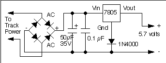 If you have used a 7805 and find that you would like a
little more smoke at the risk of reduced smoke unit lifetime, you can
boost the output voltage of an existing 7805 by 0.7 volts with the
addition of one diode instead of substituting an adjustable regulator.
The diode fools the regulator by offsetting its reference voltage and
the output will go to 5.7 volts. If you want more output, it is better
to change the regulator to an adjustable version as shown below.
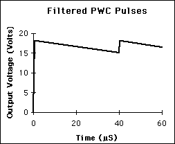 The key to this circuit is the 50 microfarad
capacitor. This is the device that stores charge to allow a fairly
constant input voltage, as shown in the diagram, so that the regulator
can do its job. Since the load current for most lights and smoke is
essentially constant, the capacitor discharge current is nearly
constant also resulting in a linear decrease in voltage with time
between the pulses. Higher load currents or smaller capacitors will
cause the voltage to decay faster. 50 microfarads is enough for most
applications, but you can use more if you'd like. The voltage rating
should be at least 25 volts with 35 volts preferred. There is some
overshoot in the PWC pulses (not shown on the diagrams) that will cause
the capacitor to charge to nearly 30 volts under zero load.
Electrolytic capacitors are polarity sensitive, be sure to install them
with the polarity markings as shown or you will experience an
unpleasant surprise when the capacitor bursts.
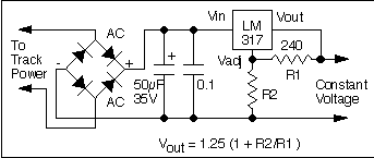 This circuit is similar to the one
above, but it uses a different regulator circuit, the LM317 (Radio
Shack 276-1778) that has adjustable positive output voltage. Depending
on the input voltage, outputs of 1.25 volts to 37 volts are possible.
The output voltage is determined by the ratio of R1 and R2. R1 should
normally be 240 ohms, use the formula given to calculate the value of
R2 for whatever voltage you want.
Remember the neither of these circuits can produce more output voltage than their input voltage. Further there is an "overhead" voltage of about 2 volts that the regulator needs to work properly. Therefore, the input voltage needs to be at least 2 volts more than the desired output voltage.
The 0.1 microfarad capacitor is optional. The 7805 and LM317 regulator circuits are sensitive to the impedance presented at their inputs. If it is wrong, the circuits may oscillate and not work correctly. If you mount the 50 microfarad capacitor right next to the circuits, you can probably omit the 0.1 microfarad capacitor and get away with it. However, an oscillating regulator circuit will be hard to diagnose without the proper equipment so my recommendation is to use it anyway.
The regulators in both of these circuits can get quite warm during operation. The typical regulator dissipation will be on the order of 3 watts while driving an LGB smoke unit or one heavyweight car's worth of lights, so some form of heat sink is required. You can buy a preformed heat sink (Radio Shack 276-1363) or you can make one yourself out of a couple of square inches of aluminum or brass sheet. If you can't hold your finger on the heat sink after a few minutes of operation, it's too small. The regulator itself won't be damaged by getting to hot, it'll shut itself down to protect itself, but your smoke or lights will stop working until the regulator cools down.
 If
you've added one of these circuits to a loco to improve smoke
performance, you can take further advantage and get better headlight
performance as well without changing out the bulb to 5 volt unit. This
is an example of how to wire a Bachmann Big Hauler. The headlight is
nondirectional and runs at nearly full intensity even at a crawl. Due
to the headlight, the overall current is higher so the filter capacitor
is increased to 100 microfarads.
A standard Big Hauler headlight has a 12 volt bulb so that it runs fairly bright at low speed with PWC anyway. However, the price of this performance is that it is too bright at high speeds and will quickly fail. By running the bulb on filtered pulses, it will be a little brighter than a standard headlight at low speed, but it will not get overly bright and burn out at high speed. The resistor is there to set the maximum intensity.
30 Oct 1999.