This website has been archived from TrainWeb.org/girr to TrainWeb.US/girr.
This website has been archived from TrainWeb.org/girr to TrainWeb.US/girr.

 21 Oct 00
After a break in and a new drive shaft supplied by Bachmann, the Climax became a fine running engine. However, out of the box it did not run very smoothly at slow speeds. After a few hours of break in running, it did better but it was still not as smooth at low speed as the Shay was out of the box. Motor and gear noise is audible, but barely. There is an audible clacking which seems to be coming from the cylinder assemblies. I would guess that this is a result of the piston rod pressure on the sound switches inside the cylinders.
At several points in the break in period, the engine developed a low speed squeak that was timed with the piston rod movements. Since ALL of the valve gear and shafts run with this period too, it was difficult to determine what the squeak was. The engine did seem to bind up a little when it was squeaking the worst. If the engine was allowed to sit for awhile, the squeak would go away. However it tends to return again after the engine has been run for a period of time. This indicates to me that the squeak is caused by something heating up, expanding and rubbing. Other individuals have reported the squeak as well and a few people have indicated that it seems to be coming from the driveline power take off (PTO) gearing. Eventually, the squeak went away.
The engine tracked well on my outdoor layout, it only derailed when it piled up a big stack of dried ivy leaves in front and then got them hung up in a turnout. It ran clean over an ivy stem across the track. It hopped like mad, but it came back down on the rails.
Indoors, I found a different story. The Climax is a stiff engine and is intolerant of out-of-level track, much more so than the Shay. The trucks are apparently not able to rock sideways enough to work over poorly leveled track. There were several places on the indoor layout where it derailed badly. It is true that the track was badly out of level, but I never knew it because everything else ran fine over that same track and it had probably been that way for years. I leveled these sections and the engine ran fine over them. When the track is out-of-level, the engine rocks badly. You can see this in a couple of spots on Bachmann's video tape.
Bachmann recommends a break in period running light. After about 8 hours of break in, I ran my standard tractive effort test, results are at Tractive Effort Tests. I expected the Climax to pull somewhat better than it did, but it did OK. The Shay will pull 23 cars in this test, the Climax handled only 11 under the same conditions.
The engine runs fine on 2' radius curves although a front truck derailment on a 2' curve will often cause the front driveline to come apart.
DC current is average. At 16 VDC, the Climax draws about 2 amps in full slip and about 5 amps at a near stall. Like the Shay, I couldn't actually stall the engine because it is just geared too low. This is a slow running engine as well, top speed is probably near 25 smph, which is somewhat faster than a real Climax could ever go. The Climax runs as close to the Shay's speed as could be expected. They doublehead with no difficulty.
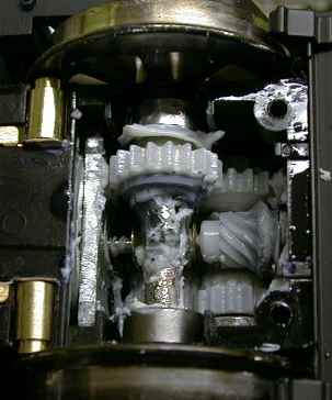 The gearing for the Climax is similar to the Shay,
except there are even more gears crammed in there. The motor worm
(mostly hidden under the axle) engages a gear on a intermediate shaft
deep in the housing which has two other gears on it. The gearing on the
top side eventually drives the axle. The gearing on the bottom side
ends up driving the driveline. The gearing on the other end of the
motor is a little simpler because there are no driveline gears at the
other end. Note that there is a bracket on the truck bottom cover that
MUST be oriented so that it supports the driveline
gear when the cover is reinstalled.
The grease that is in there is what is left over AFTER I removed about half of it so that I could see what I was doing while trying to apply oil to the two intermediate shafts and bearings. Since this picture was taken, I have removed all the Bachmann grease that I could and relubed the trucks with LGB 51020 gear grease and 50019 special oil. After only a few more minutes of run time, I noted a pronounced improvement in very slow speed performance.
The Climax is equipped with a standard Bachmann smoke unit driven by a voltage regulator, see the section on smoke below. The stock stack is a little too small to accept an LGB smoke unit. Bachmann recommends that the smoke not be used if the track voltage is to exceed 16 VDC. This recommendation is a little odd, because the internal regulator should protect the smoke unit at high input voltages. It never did make much smoke at all, but this was due to a problem in the voltage regulator.
Some units of the Bachmann Shay had serious reliability problems with the wheel bushings. They would simply disintegrate and the wheels would get loose and start flopping around. Neither of my Shays has had this problem. I have been checking the Climax for this problem also. After several hours of operation, all the wheels are still tight on their axles and are apparently in good order.
Ross Webster has described his DCC conversion at DCC INSTALLATION IN THE BACHMANN CLIMAX. I finally did a DCC installation in my own Climax, see DCC in the Climax.
[ Top ]
After approximately 20 hours of break in, the Climax settled down and has not changed much with more break in. The squeak hadn't been heard in awhile and slow speed performance had settled out to only fair. The slowest it will reliably go is about 1 second/tie. I can get it to run at 2 sec/tie, but only for 6" or less before it stalls with the lights still burning dimly.
Since the driveline is hard (see the section on Driveline Issues below), there has been a lot of discussion about the potential for binding in the driveline. While I can detect that my unit has some driveline binding at times, this does not appear to always be the case. Once the engine has stalled, I can rotate each U-joint slightly by hand to see that neither of them is bound up so this is not the cause of this particular problem. Further, by disconnecting both drivelines and letting the rear one drag on the track, the slow speed performance of the engine is unchanged. With both drivelines disconnected, I find that the load of the central gearbox is probably low enough that it could be driven by one truck. I do not know how tight the box was when it was new. I can feel some rotational resistance but it is fairly light and uniform.
I must conclude that the remaining binding that it causing the stalls has to be within one or both trucks.
Some users have reported that the motors run very hot after only a short run time. This does not seem to be the case on this particular unit. The motors are warm after extended running, but certainly not hot. I estimate the temperature of these motors at less than 40C.
[ Top ]
 Electrical power is picked up on all eight wheels with a ball type
contact similar to the Shay except that the Climax contacts are
enclosed in brass holders instead of plastic ones. While I was running
the engine with a Kadee contact brush, I found that one of them was
flaky and tended to spit fire.
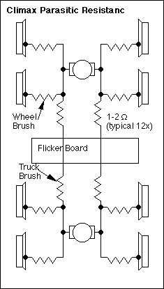
Power is transferred between the trucks and the engine frame with brushes on the tops of the trucks that ride on crescent shaped contact plates on the underside of the loco frame. These contacts appear to have 1 or 2 ohms of resistance each. Normally this would not be a problem since each motor draws power primarily from the wheel pickups in its own truck. However, when track contact is lost on a truck, power is borrowed from the other truck through these contacts until full track contact is restored. This means that one motor has full track voltage and the other motor has several volts less due to voltage drop through four contacts. The motors then try to run at different speeds which causes a torque transfer between the trucks through the driveline. See the driveline comments below for more information on this potential problem.
The voltage drop in these contacts is also a potential cause of unsteady running at very low speed. If one truck loses electrical power pickup when the engine is running very slowly, that motor cannot get enough power (due to the frame contact resistance) from the other truck to keep running and it stalls. The mechanical load on the other truck then increases and it stalls too. The engine will stop but with the headlight still dimly on indicating that some power is getting to the engine. Carefully touching a small screwdriver to each wheel and rail may find a wheel that lost contact and the engine will restart. Further evidence that the truck brushes are significantly involved in the unstable slow speed running is that the engine will do better on freshly cleaned track.
I would suspect that battery power or DCC folk will probably have to hard wire the motor power and bypass the frame contacts to avoid the unnecessary and potentially damaging voltage drop. When the engine is run from battery or DCC power, the full level of current for one motor would flow through these contacts all the time and they would get quite hot. Assuming 1 ohm of contact resistance and an amp of current for one motor, a watt of heat would be dissipated in each contact. A watt would be enough to cause the truck contacts to melt their plastic mounting feature in the truck bolster. This very result has been reported.
Rewiring the engine is somewhat involved but it can and should be done during a battery power or DCC installation. The trucks can be hardwired around the contacts, but that makes it difficult to remove the trucks later. Another method is to just wire around the bolster contacts as shown later in this page at Truck to Frame Connection Modifications. A better method is to modify the trucks and bolsters to jump around the contacts AND add separate motor connections as shown even later in this page at Wiring the Climax Motors for Command Control.
Eventually the wheel contact that tended to spit fire failed completely. The spring inside the contact overheated (evidenced by a brown discoloration and a collapsed section) and the contact force was reduced enough so that the ball bearing did not bear against the wheel. The spring was sufficiently damaged that it needed replacement.
The Climax wheel contacts are easy enough to remove. With the truck bottom cover removed, the contact assembly can be simply pried out with a small screwdriver. The ball, piston, spring and housing can then be disassembled and inspected. Note that the piston ridge is not symmetrically placed, the longer end goes into the spring. If the spring looks brown, it should be replaced. A bad spring will loose tension. If you try to stretch it, it'll yield at low force. A spring in this condition is useless.
If you've rewired the bolster contacts as described later in this page, the four springs that were removed can be used for replacements. Lacking those, the springs used for LGB track sliders work too. They are quite long so that you can cut one in half to make two replacement springs. If a spring is just a little bit short the piston can be reversed so that the short end goes into the spring.
[ Top ]
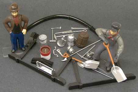 The Climax is equipped with a lot of fine detail
features, mostly of metal. There is also a bag full of goodies that can
be placed anywhere on the engine. The pilot steps must be added by the
user. The bottom of the end beams must be removed (two screws) to
install the steps. I had to rotate the siphon hose fitting on the
bottom of the tender to get the hose to fit.
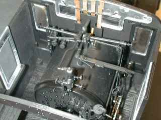 The back head is quite well detailed with
lots of levers, pipes and valves. Unlike the Shay, Bachmann connected
the valve gear to the Johnson bar in the cab. You can access the
Johnson bar by working through the cab window and the front cab door.
You have to lift the bar a little to move it. I like this feature, all
of the valve gear parts move just as they should. Of course the valve
gear has no impact on the actual operation of the engine. The effect is
visual only.
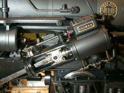 The cylinders are very well detailed with
bolt detail, cylinder cocks, complete moving valve gear and a working
crosshead. The cylinder cock valve lever in the cab actually works the
mechanism right up to the cocks themselves. The cab roof must be
removed to reach the handle.
The engine is heavily weighted with cast weights in both the boiler and the tender. The boiler weight consumes most of the center of the boiler so not much else will fit there as the smoke unit assembly consumes the rest. The tender weight is the coal load. It is cast in metal and then painted. The two tanks on the back of the tender are also cast metal.
[ Top ]
The smokestack on mine wouldn't stay on straight as delivered. There is a steam exhaust line running up the back of the stack (modeled with a piece of wire) that was bent improperly. This caused the stack to lean over until the wire was properly bent.
The front headlight has a problem staying horizontal. It seems that the wiring is a little too tight which tends to pull the back of the headlight down. I pried a little wire up and now it sits better, but is still not perfect as the plastic brackets have taken a set.
The handle on the water hatch fell off almost immediately. A little CA now holds it in place.
The engine comes with a fireman figure and another figure who looks more like a station agent than an engineer. This guy's legs don't bend so he can't be placed in a sitting position without cutting his legs off.
There were some shiny spots on the cab roof. At first I thought that these were oil patches left over from lubrication. In fact, they are polished spots where the cab roof has rubbed against the Styrofoam packaging. There are identical spots of paint left on the upper Styrofoam insert.
The wiring in this engine is still not DCC friendly. Considerable rewiring needs to be done to route motor and power wires to and from the trucks and to separate the power pickups from the motors within the trucks. This can be fixed, see Wiring the Climax Motors for Command Control.
There is precious little room in the firebox for any other circuitry besides the flicker board and its substantial wire bundle. There is also precious little room in the tender for batteries, a receiver and a sound system. Unlike the Shay, a sound system battery will not fit well under the frame because that area is now occupied by mechanism. However, a slimline battery will fit in the cab, see DCC Installation in the Climax.
[ Top ]
The ashpan contains flickering LEDs done the same way as in the Shay. The firebox door opens to reveal more flickering lights. Like the Shay, I had problems with reliable operation of the flicker circuit and I applied the same fixes. They will seem to work if more than 12 volts of pure DC is applied to the track. If there is any pulsing at all on the power, the flickering won't start.
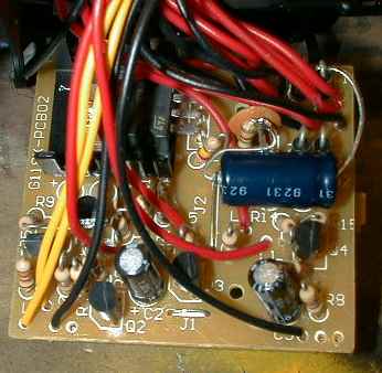 This is a photo of the
flicker board in the ashpan of the Climax. I have already added a new
capacitor to this board. The board is accessed by prying off the ashpan
cover and just pulling out the board. Unlike the Shay, this board free
floats in the ashpan. There is enough wire attached to pull the board
out far enough to work on it.
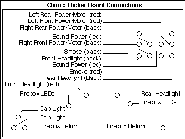 This diagram shows where that
mass of wires actually goes. These were the locations and colors of the
wires that were in my Climax. There is no guarantee that all Climaxes
were assembled the same. Usually some gentle tugging on the wires will
indicate where the other end any given wire is.
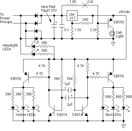 This the schematic of the board.
The fix involves adding a storage capacitor to the regulator circuit.
This change is beneficial ONLY if you use pulse power like Aristo PWC.
With linear track power, the capacitor does not provide any
improvement. The capacitor charges up on the peaks of the PWC pulses
and provides a higher average input voltage to the regulator IC,
especially at low speeds. When this is done, a lead of resistor R9 has
to be cut or the cab light will flicker badly. R9 is located right next
to the regulator heat sink. You may then find that the cab light runs
too bright. To fix that, unsolder the yellow wire that is located
between R10 and R7 and insert a 50 to 100 ohm resistor in series with
the wire to dim the light to your satisfaction.
The headlights are yellow LEDs which are visible but do not cast a beam at all. Bachmann made a change from regular bulbs to LEDs part way through the Shay production and they seem to have carried the change over to the Climax. I have changed the rear one out to a Grain of Wheat bulb while I was relocating the rear headlight. The front one was done during the DCC installation.
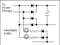 The
partial schematic shows the changes that are needed to accommodate
incandescent bulbs in place of the LEDs in the headlight and tail
light. The GOW bulbs should run at 9 volts or less. I recommend a 6
volt bulb to minimize the current that is drawn from the 9 volt
regulator on the flicker board.
The wires leading to the front and rear headlights are two red wires located near Q4. You will find these wires connected to 390 ohm current limiting resistors. Remove the resistors and insert the diodes and new resistors where these resistors were and then change out the LEDs in both headlights. Adjust the resistor value to get your desired headlight intensity with whatever bulb that you use.
To get the LEDs out of the headlights, remove the headlight housing from its base and insert a small screwdriver in the hole in the bottom of the headlight and gently push the reflector assembly out. This will press out the clear plastic lens, then the reflector itself. You can then install your new bulb by hooking it to the existing wires.
[ Top ]
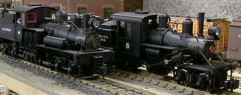 The engine is claimed to be a 1:20.3 model of a 25
ton Class B Climax. It looks about right but I don't have any drawings
to check it against. I have seen comments from others that it appears
to be as close to scale as practical.
For example, Ed Vasser writes "Basically just wanted to let you know that the Bachmann Climax is indeed 1:20.3 scale and is one of, if not the, most detailed and accurate models of a Class B Climax ever produced in any scale. I've had several HO models over the years and none of them were ever as accurate."
The engine is 4" wide and 16" long over the end beams. Since it is about the same length and width as a regular large scale box car, horizontal clearance will probably not be a problem for anybody. The height is 6-5/8" high over the stack from the railheads. The cab roof mounted rear headlight is taller, it extends 7-3/8" from the railheads.
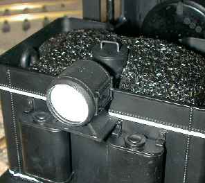 I have a
clearance problem at 7-1/4" so I have moved the rear headlight to the
rear of the tender. This involved some rewiring of the headlight and
patching of the hole left in the cab roof. The base of the headlight
assembly was attached to the rear of the tender with Zap-CA. A couple
of styrene brackets support the headlight base. The wires route through
a hole drilled in the rear of the tender tank. These wires are then
routed through the wiring tunnel under the cab and end up back at the
flicker board.
The pilot steps hang fairly low. I found a track geometry where the pilot steps can just clip an Aristo turnout motor. The steps are high enough to clear LGB motors completely.
[ Top ]
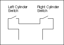 The
schematic in the manual shows that the sound switches are wired in
series as shown in this diagram. I thought that this must be a mistake
on the schematic, but it is not. The switches really are wired in
series and since the two switches never close at the same time, the
contact wires in the tender are useless. This would need to be fixed
before a sound system could ever work with the switches.
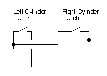 Fortunately rewiring the switches in parallel is fairly easy. The
upside is that both switches will close the chuff circuit. The downside
is that since the cylinders are quartered, the chuff sequence obtained
is chuff-chuff-nothing-nothing.
If you actually want to make them close, all that is needed is to add one wire between the cylinders. Pop both slide valve covers off the cylinders and thread a wire out wire access hole in the side of one cylinder and back into the wire access hole on the other side. It takes a bit of patience, but a 24 GA wire will go in fine. It is probably easier to use a solid wire than a stranded wire because it is stiffer and easier to push through the holes. On the side with two black wires, unsolder one of them and solder it back to the terminal with the other black wire. Connect the new wire between the red wire on the other side of the engine to the now empty terminal and you are done.
Even when the switches close, it is unclear that they will be much use due to the funny timing.
[ Top ]
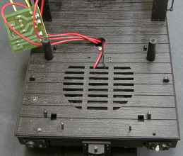 The Climax tender
is quite small, about 2/3 the volume of the Shay tender. There is space
for a speaker on the floor. Since the tender is so small, it looks like
the largest speaker that will actually fit is about 2.5". The same
connection board as found in the Shay is also in the tender, but it is
simply floating free.
The tender mounting screws are under the water valves which must be removed to access the screws. When I tried to pull mine, the valve handles came out of the valve bases. I had to pry the valve bases out as the paint has apparently welded them in place. Once they were removed the first time and the handles cemented back in the bases, getting them out again was no problem.
Once the screws are removed, the tender must be rotated back to release the clips in the back. There is a handrail on the rear of the frame that must be removed to allow the tender shell to rotate far enough.
I purchased a Soundtraxx Sierra sound system which is especially configured for the Climax. The board is identical to other Sierra boards, but it has recordings appropriate to the Climax. It also comes with a small oval speaker that will fit into the Climax tender. The Sierra is a high end sound system and will provide excellent results when properly installed.
The Sierra comes with very complete instructions and I had minimal difficulty with the installation, although I did make some changes.
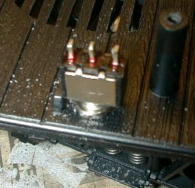 One
change I made is the exact location of the power switch. I didn't use
the supplied slide switch because the handle is too short and I
wouldn't be able to reach it up between the frame rails. Instead I used
a sub-miniature toggle switch. The 1/4" mounting hole should be drilled
at 2" from the rear of the flooring about 3/8" in from the edge. This
centers the switch between the frame rails so that the nut just fits
between the rails and the switch body just clears the tender shell.
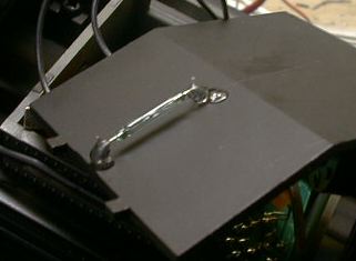 Since the Bachmann
supplied chuff switches do not work very well, Soundtraxx provides a
reed switch that is mounted on the bottom of the ashpan cover. The
reflective foil that surrounds the holes drilled for the switch leads
should be trimmed back so that there is no possibility of a short to
the leads.
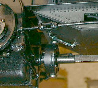 Two magnets are
attached to the U-joint at the rear of the gearbox. If the switch is
mounted properly, the magnets will get close enough to reliably trigger
the switch. The magnets should be attached to the U-joint with CA right
next to the two screws in the U-joint. If you try to mount them
elsewhere, they will tend to jump to be near the screws before the CA
has had a chance to set. After a quick coat of engine black, the
magnets become much less visually obtrusive.
The gear ratio in the gearbox is 1:1 so that with two magnets, the chuff rate is half of the prototypical rate. You can mount two more of your own magnets on the U-joint, but the Sierra really can't keep up with the prototypical chuff rate.
I did notice that the system would skip a beat once in awhile in 2' radius curves. I assume that this is due to the wobbling of the U-joint when it is operated off axis.
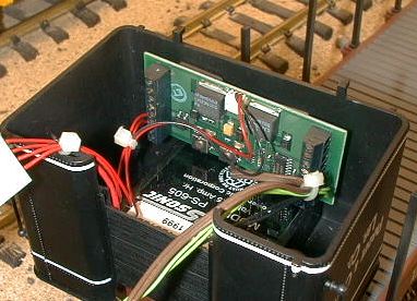 The
Sierra's instructions call for mounting the sound board to the rear
tender wall with "Superlock" tape. This stuff is something like Velcro.
However, my set didn't come with this material included so I devised
another mount. The Superlock tape is intended to allow the board to be
removed to allow access to the programming switches. However, I didn't
like this approach because the board would be floating around loose
while I was trying to press switches on the board. This seems to me to
be asking for trouble. Instead, I mounted the board with the switches
and LED's facing outward. One small piece of foam tape attaches the
micro controller chip (the one NOT in the socket) to the rear tender
wall. This allows the switches to be accessed with the board mounted
and secure.
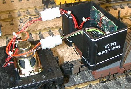 I wired the unit
with connectors so that I could entirely remove the tender shell
without anything but connectors dangling. I can flip the tender over on
a following flatcar so that I can test and program the unit.
Programming can take some considerable time and effort so access to the
switches is necessary. See my Sierra Tips page for more information
on programming the Sierra.
There are lots of wires that go between the sound board and the loco. I used ten, eight for the sound board and two for the remounted rear headlight. If you use the external volume control, there will be three more. Adding the firebox flicker will add another three. Coupler clank will add two wires. Up to five more wires may run to external reed switches to magnetically control some sound effects. This can be a big bundle so plan your installation carefully and be sure to leave enough wire to allow the tender shell to be easily maneuvered. Any wire that is there will also have to be bundled back into the shell when the tender is mounted, so don't use too much.
The supplied speaker is mounted on a cardboard gasket so that it can seal to the floor and still allow the wires to the rear truck to escape from under the speaker. The instructions indicated that a supplied template should be used to cut the gaskets. Mine didn't come with a template so I cut my own using the speaker as a template. I used parts of the box that the Sierra came in for the card stock needed to make the gaskets.
The speaker doesn't cover the last row and a half of slots in the floor so I sealed them with black electrical tape.
The overall sound quality of the installation in the Climax is not quite as good as the installation that I did in the C-16. I attribute the difference to the speaker. I have attached a good, enclosed, speaker to the Climax and it sounds better. The chuff is deeper and has more authority. As much as I've tried, I just can't make the larger and better sounding speaker fit. After considerable hacking on the speaker itself, it fits by itself but it won't fit with the battery and sound board in there too. The height misses by about 1/16" and the sound board presses against the speaker. Swapping the position of the sound board and the battery won't work either because then the battery won't fit behind the speaker. With the larger speaker, tender just won't close.
[ Top ]
The coupler mounts are pretty strange. This is a new design for Bachmann. None of the existing knuckle or hook and loop couplers will attach to this mount without modification to both the mount and the coupler. The screw that attaches the coupler mount is hidden behind a little plastic cover that slips out fairly easily. Hook and loop couplers are not supplied with the engine.
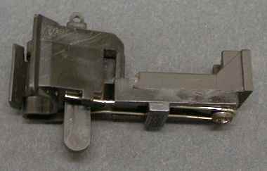 I mounted LGB
knuckles by cutting off the end of the mount just behind the round boss
at the end. The LGB knuckles were ground down at the back end right to
the end of the spring. The two ridges along the tang were ground down
flush all the way to the knuckle. A new mounting hole was drilled in
the mount and the coupler was attached with a single screw. Since there
are no features left to keep the coupler from rotating around the
mounting screw, I used a small cable tie to prevent rotation. This
photo was taken before the tie was installed. Alternately, the coupler
could be secured with some hot glue right at the end of the coupler
mount and behind the knuckle.
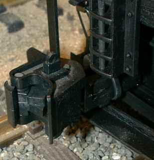 After the coupler is mounted, the painted
cable tie can hardly be seen. There is minimal clearance between the
coupler and the link and pin sockets so it won't be possible to mount
the coupler any closer. Mounting a Kadee #831 will involve some similar
gouging on both the coupler mount and the mount. Body mounting couplers
shouldn't be too hard but some sort of bracketry will be needed. A
knuckle could even be made to fit into one of the link and pin sockets
as it was sometimes done on the prototype. There are instructions on my
Shay Tips page for this kind of
mount on the Shay.
[ Top ]
The driveline on the Climax drives the central gearbox and cylinder assemblies from BOTH trucks. This is a departure from the Shay which drove the engine assembly from only the front truck. Perhaps Bachmann thought this was necessary due to extra gear load of the Climax gearbox relative to the Shay. The POSSIBLE downside of this change is that the driveline could be placed under considerably more force than in the Shay under some adverse conditions. If for some reason one of the trucks stalls, either due to an electrical or mechanical problem, the other truck will also stall through the driveline. This COULD place enough force on the driveline to break it. I have heard of one case where the driveline did indeed break. If you turn the engine over and connect power to the engine and run it slowly and you mechanically slow one truck by loading it with your finger, you will see the other truck slow down as well. This implies that the driveline is transferring torque and loading the other truck.
There is another possible driveline problem related to the U-joints. When a U-joint is operated off axis (for example when the engine goes through a curve), the speed of rotation of the square shaft changes twice each revolution. If the second U-joint is oriented 90 degrees to the first one AND it operates at exactly the same angle, these shaft speed modulations will be corrected.
On the Shay, the two joints on a square shaft do not bend at the same angle all the time so that there is imperfect speed cancellation resulting in some net speed modulation of the engine shaft. It is normally so small that it is not noticeable. If the front shaft ends are not oriented properly with respect to each other, these speed modulations will add instead of nearly cancel. It is easy to misconnect the shafts because the engine assembly will freewheel when it is disconnected from the front truck and it can be rotated by hand. The result is significant speed modulation of the engine shaft such that it can be detected by eye or by ear if a sound system is installed. However, no damage results.
Note that these driveline speed compensation issues occur on prototype Shays as a normal behavior. It is not a major problem because real curves are not nearly as sharp as ours and the driveline is easily strong enough to handle it. The result on a real Shay is that the front or rear truck wheels slip a little to relieve the stress. The extra forces applied to the driveline do tend to bind it up a little and make an improperly lubricated square shaft resist expansion or compression and therefore resist truck rotation. This is one of the reasons that Shays deserve their reputation as "rail spreaders."
These driveline forces in the Shay were one of reasons that the Climax and Heisler locomotives even exist. The centered and symmetrical driveline on these engines naturally tend to cancel these forces and do improve tracking.
On the Climax, the shafts are centered and the U-joints tend to have the nearly the same angle as the truck rotates allowing them to do their speed compensation quite well. However, if for some reason, the shafts get rotated 90 degrees from the way they were originally installed, the speed errors caused by the U-joints will add and the U-joints will try to modulate the speed of the central gearbox. However, the other truck will be trying to run the central gearbox at a nearly constant speed and they will fight each other by alternately loading and unloading the driveline. This is a bad situation and would surely result in rapid driveline failure somewhere.
Unless Bachmann has been very careful in the assembly of the Climax, I can speculate that some units could be shipped with a driveline alignment error. Maybe it won't happen at all, but if your unit seems to bind up, especially in tight turns, this may be the cause.
Mine came out of the box with the front driveline disconnected, but since neither part of the slip joint will turn easily, it appears that just reconnecting the driveline caused it to go back together properly. Since I notice no difference in performance on tight curves vs. straight track, I would conclude that on a properly configured Climax, this is not a problem. Difficulties will only arise with something upsets the proper configuration of the driveline system.
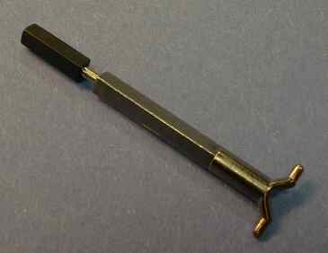 Bachmann is recognized this weakness in their
initial design and provided an effective modification that prevents
driveline binding. A replacement rear shaft is available free for the
asking from Bachmann. This shaft replaces the hard metal end of the
shaft with a plastic collar around a round pin. In the photo, the
collar is pulled back a little to show the pin. The collar is a tight
fit on the pin but it still can slip creating a sort of a friction
clutch. The rear truck can still contribute to running the central
gearbox, but the friction clutch will prevent serious forces from
building up.
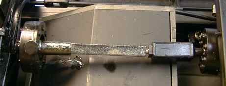 The
shaft simply replaces the old shaft. Mine didn't come with any sort of
instructions, but it is easy to replace. Simply disconnect the rear
shaft from the rear truck so that the U-joint can be rotated to provide
straight in access to a jewelers screwdriver. Remove the two small
screws on the rear of the U-joint at the rear of the central gearbox.
Pull off the rear ring of the U-joint and pull the old shaft out of the
ring. Put the new one back in the ring and reassemble the U-joint.
This modification really does work. If power is applied to only one truck, it will run faster than the other one due to the contact resistance mentioned above. Without the modification, the driveline used to bind up right away. With the modified shaft, the collar slips like mad, but the force on the driveline never builds up enough to endanger the mechanism.
My Climax had been running pretty smoothly before so I didn't notice much of an improvement, but the occasional driveline binding that I observed before will no longer be a reliability problem.
[ Top ]
Dennis from Hillside Railways sent me a series of pictures and descriptions of how he hardwired the trucks to the frames to eliminate the potentially troublesome brushes that the engine comes with. I feel that this modifications is probably mandatory for anybody that wants to run the engine from an onboard battery or with DCC to prevent the unnecessary voltage drop that the stock contacts add and to prevent probable meltdowns of the contacts. Hardwiring the trucks makes the trucks more difficult to remove from the engine, but it will make the engine run better and reduce a significant source of potential mechanical stress from the driveline.
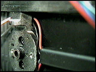 These are all viewing the rear truck bolster
mounting. This one shows where I tucked the wires from the channel to
the rear of bolster. As you progress through these, you will get a
better view of what I've done.
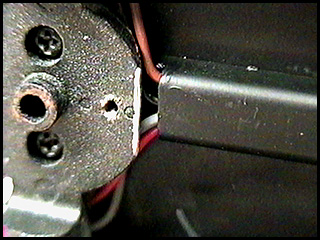 Here's a view of the wires exiting the
channel. Notice that I trimmed a portion of the frame too better
accommodate the wires.
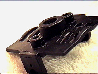 Here's a shot of the top motor block saddle.
Notice that the contacts, springs, barrels, etc. have been removed. I
drilled the hole in the side to reduce the kink in wire exiting and
making the loop to the insides of frame.
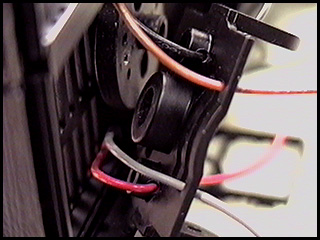 This view is of all four wires going through motor block
piece.
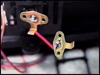 On the clips inside, simply drill a hole
in the middle and solder the wire to it. Screw it in place and you're
all hooked up again. I replace all the wires with 24 GA. and resistance
problems go away.
[ Top ]
In the section above, Dennis described a method for wiring around the Climax troublesome truck to frame contacts. However, his modification still leaves the motors connected to the power pickups in the trucks. It would be possible to add two more wires around the bolsters, but then the trucks would be wired to the engine making removal later difficult.
In this section, I describe another method which I have used to wire the motors separately, eliminate the contacts and STILL retain easy removal of the trucks.
To do this modification, the trucks need to be removed from the loco (see page 28 in the Climax manual). Further, the sideframes must be removed from the trucks. Removal another screw at the center of the sideframe and two small screws at the ends of the sideframe to release the sideframes.
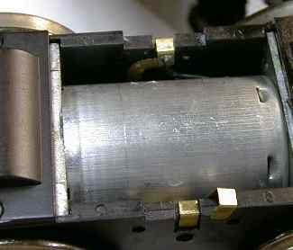 The
Climax truck contacts are not arranged quite as nicely as on the Shay.
The power pickup contact is a strap that hooks over the top of the
truck. The motor contact is a second U shaped piece that fits over the
power pickup contact. The lower motor contact in the photo has been
removed from over the top of the power pickup contact.
The
Climax truck contacts are not arranged quite as nicely as on the Shay.
The power pickup contact is a strap that hooks over the top of the
truck. The motor contact is a second U shaped piece that fits over the
power pickup contact. The lower motor contact in the photo has been
removed from over the top of the power pickup contact.
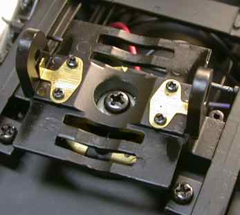 Two brass contact strips on the truck
bolster reach around the upper edges of the truck and make contact to
both the motor and power pickups. Underneath the bolster are two spring
loaded contacts that touch two crescent shaped contact plates on the
frame. It is these spring loaded contacts that cause so much
trouble.
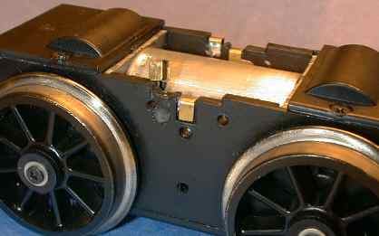 My
version of the modification involves adding another set of contacts to
the truck and bolster. Actually on the truck, the motor contact is not
new, it is just moved. A groove similar to the one already there is cut
next to the existing contact. I used a Dremel tool with a 1/8" metal
cutter bit and cut the groove with sort of a hand held end mill
approach. The tool should be run at minimum speed and held steady. The
cut is easy to do because the cut has lots of tolerance.
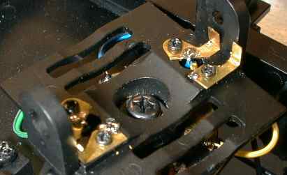 The bolster is modified to add two
new contacts that align with the moved motor contact. The new contact
is fabricated from brass strip stock. I made these literally by hand
with a rail nipper tool and a small drill. The new contact is attached
with one of the existing screws in the existing mounting hole. The
existing contact is trimmed to clear the new contact.
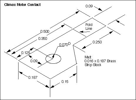 This
drawing can be used to fabricate the new contacts. Note that they are
"left" and "right" handed, you'll need two of each. Fold two of them
upward on the fold line and two of them downward.
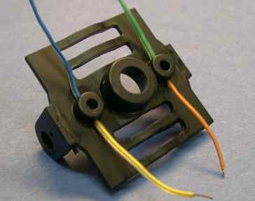 Holes are drilled
into the sides of the old contact holders to allow horizontal wire
access. The power and motor wires are pulled up through the old contact
holes and soldered to the four contacts. Since I haven't installed
command control (yet), I just soldered both the motor and power wires
to the corners of the crescent contact plates on the frame. Eventually,
I'll extend the motor wires to a DCC decoder.
The result of this modification is that the engine runs more smoothly at very low speeds. Unlike with the stock truck contacts, if power is applied to one truck, BOTH trucks start and run at the same voltage, not just the one which was getting power.
[ Top ]
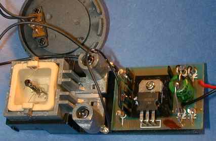 The smoke unit in
the Climax is similar to other Bachmann smoke units, but this time
they've added a twist. The smoke unit runs from its own constant
voltage regulator. The regulator is mounted on a circuit board attached
to the smoke unit. Inclusion of a voltage regulator limits the maximum
voltage that the smoke unit can experience and therefore limits its
maximum temperature. This should improve the life of the smoke
unit.
Although this is a step in the right direction, the smoke unit still runs at about 12 volts, so it takes more than 14 volts on the track to get it fully going. At this voltage, the Climax is moving right along. Maybe a future regulated Bachmann smoke unit will run at lower voltage to allow better smoke at lower speed while still maintaining some improved level of reliability.
However, all is not well with this circuit. The smoke unit in my Climax never worked very well. I had assumed that the problem was a combination of a smoke unit set at too high a voltage and the extra voltage drop due to the truck to frame contacts and I never even looked at it. As it turns out, my smoke unit regulator was oscillating because Bachmann failed to include a necessary bypass capacitor for the LM317 regulator. Without some form of bypassing, the LM317 will often oscillate and mine did. An oscillating regulator will fail to regulate properly. The lack of this capacitor does not guarantee that an LM317 will oscillate, it just makes it more likely.
The manufacturer's data sheet specifies that if the regulator is more than 6" away from the nearest bypassing, then a 0.1 uF or larger capacitor should be installed across input of the regulator to assure its stability. To add this part requires that the smoke unit assembly be removed from the boiler.
The smoke unit can be easily removed from the boiler.
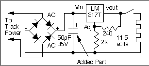 This is the schematic of the
regulator. It is completely straightforward. The voltage is nominally
set to 11.67 volts, mine generated only about 8 volts average until the
capacitor was added. After the capacitor was installed, it settled to
11.5 volts. If Aristo PWC is used, then a 50 uF capacitor can be used
to improve the smoke output at low speed. With PWC, the smoke unit runs
at full smoke at moderate speeds. This configuration does not work
nearly as well as an LGB 5 volt regulated smoke unit, but it is much
better than without the capacitor. If linear power is used, then a 0.1
uF capacitor can be installed instead.
Solder the plus lead of a 50 uF capacitor to the top lead of the diodes at the bottom as shown on the photo above and the negative lead to the bottom leads of the diodes at the top of the photo.
The smoke unit draws 150 mA while running at 14 volts or above. It also runs fine from DCC without any changes other than adding the bypass capacitor. It remains to be seen if these regulated smoke units will hold up any better than the standard Bachmann smoke unit.
If the regulator works properly, but the unit still smokes weakly, it may be possible to improve the smoke output at zero cost, see my Smoke Tips page for details. The downside is that it may go through smoke fluid faster and be even more likely to burn up if it runs dry.
[ Top ]
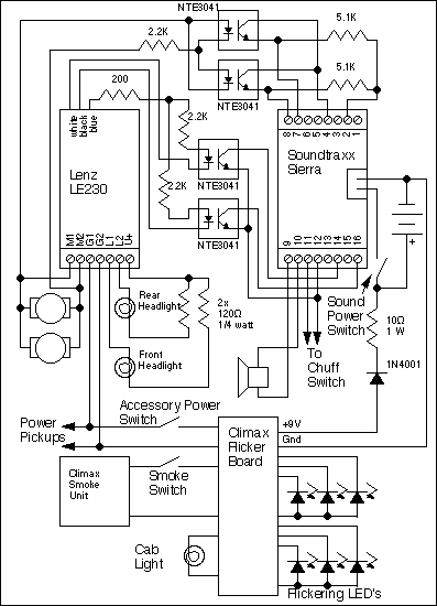 After I had gone
to all the trouble to isolate the motors from the track pickups, you
could probably bet that a DCC installation would not be far behind. It
wasn't. I elected to install DCC using an Lenz LE230 decoder to allow
the back-emf capability of the decoder to smooth out the rest of the
slow speed issues with the Climax. This worked very well.
The schematic of the installation is almost identical to the installation that I did in the Shay. I have retained the Bachmann smoke unit that now seems to work ok and also because an LGB unit won't fit in the small stack. The headlight bulbs have been changed out to Radio Shack parts (p/n 272-1092c) so the series resistors are a little different than with the Shay's bulbs. I also added a 200 ohm resistor in series with the DCC decoder blue wire to act as a current limiter/fuse in case of a short in the accessory circuits.
The operation of the circuit is described in my Shay Tips page so I won't go over it again here.
I still hadn't given up on the larger speaker and I was willing to make one more try to cram it in there. Since the sound system by itself barely fit with the smaller speaker, it might seem unlikely that a DCC decoder could even fit in there too, much less with a larger speaker. It all does fit....just barely. This was the hardest installation that I have done yet. However, boys and girls, we are professionals, please don't try this at home.
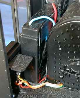 The key is
moving the battery. With DCC the battery is not really necessary, but I
elected to retain the battery to allow the sound system to operate
properly while the loco is running on regular track power. The battery
has been moved into the cab on the fireman's side. A corner of the
slimline battery can be seen through the fireman's side window, but
since it is black, the battery doesn't show up well and is visually
acceptable. The sound system power switch is mounted in the cab floor
on the fireman's side and the wiring is run through a hole drilled at
the base of the backhead into the firebox. The wiring is also
unobtrusive after being painted black. The battery charging resistor
and diode are mounted in the back of the switch under the fireman's
seat and are well concealed. The old sound system power switch that was
in the tender is now used to disconnect all the flicker board circuits
to allow the decoder to be programmed on a programming track.
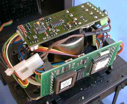 Once the
battery is out of the way, the larger speaker will fit, provided that
it's frame is gouged sufficiently to fit between the tender shell
mounting posts.
I was never totally happy with the Soundtraxx recommend method of mounting the sound board on the rear tender wall. This results in lots of wires that have to go between the frame and the shell. Since adding the DCC decoder would add even more wires, I concluded that the sound board would have to mount on the frame somewhere so that the wiring could be cleaned up and not take up a bunch of room by itself. The Sierra board is now mounted behind of the speaker with a small strip of Velcro so that the Sierra can be peeled off and laid down to access the controls on the board. The LE230 is mounted with Velcro across the back of the speaker magnet. A downside of mounting the LE230 this way is that the switching FETs don't get good air movement for cooling, but they usually don't get really hot anyway and they are marginally heat sunk to the circuit board. The decoder does get quite warm to the touch during normal operation, but not hot enough to cause alarm.
All this stuff is a very tight fit. The speaker frame is hard by coal bin in the front, and the sound board barely fits between the speaker and the shell at the back. The LE230 just clears the top of the shell and the wire bundle that comes up through the floor barely fits under the coal pile at the front.
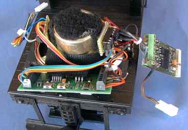 Since the LE230 has hardwiring only on
one end, the function wiring plug can be pulled and the LE230 can then
be rotated sideways to access the wiring terminal screws. Wiring to the
sound board is arranged to crisscross behind the speaker so that the
sound board can be pulled back without stressing its wiring. The
optoisolators are mounted on both sides of the speaker magnet, again
with Velcro. All this Velcro allows each part to be peeled out for
access if necessary.
By using the back-emf capability of the LE230, the engine runs very smoothly at the lowest speed step and it will not stall. Even if the engine's movement is blocked, the decoder increases the motor power and the engine slowly slips all eight drivers at the same speed as when the engine was moving.
[ Top ]
30 Oct 1999.
© 1998-2002 George Schreyer
Created Dec 17, 1998
Last Updated June 30, 2002