Possible Mars Light in the 5771
A lot of this is supposition based on a SBWR-5000 light at the Indiana Transportation Museum - which was missing the MOTOR, GEARBOX, and LINKAGES at the time the photos were taken. I have tried to put together what looks like - what should be as far as mounting of these parts based on other lights.
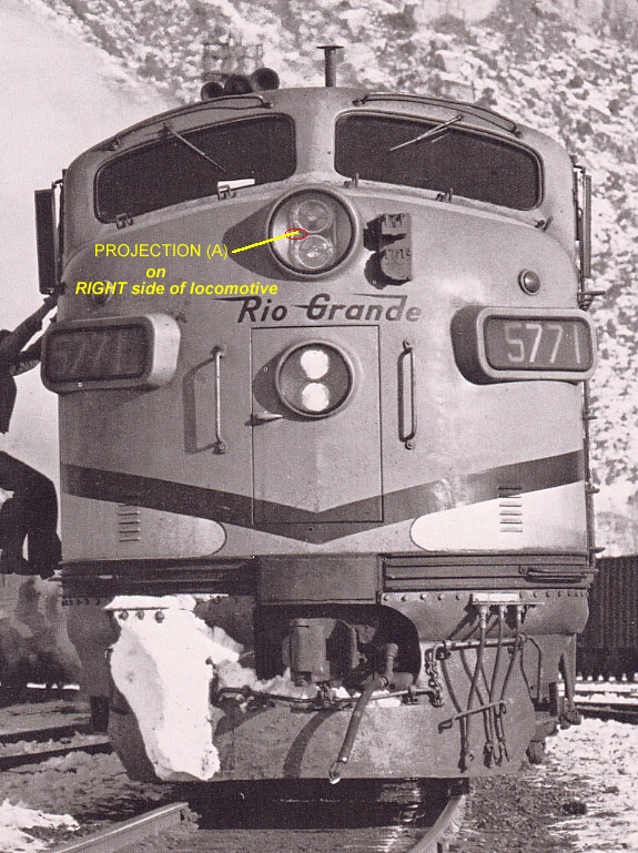
Projection (A) is seen below also. It is structure on the outer oval ring to which one of the rods from the gearbox is attached.

One rod from the gearbox should be attached to Projection (A) and the other to Projection (B). They should both be
attached so that LINKAGE ATTACHMENTS are towards the BOTTOM of the light...in other words the bolt heads holding the
rods on these projections are towards the Bottom of the Light.
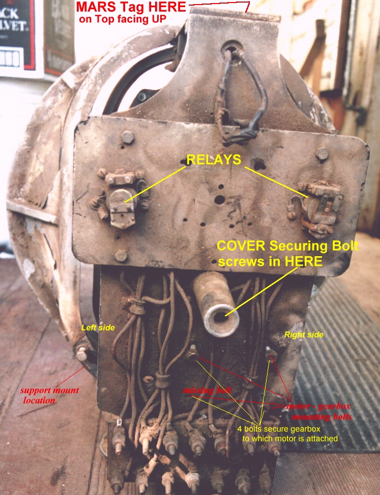
This is a Red-Clear light so the light in the 5771 May NOT have the relays. The 4 bolts and holes that hold the gearbox to the plate are seen showing that the mounting is toward the RIGHT side of the light.
The motor is mounted to one end of the gearbox.
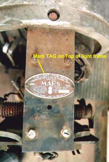
This is the TOP of the light showing the location of the Mars TAG it has the model and serial number on it.
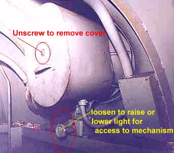
This shows the possible back view of the light with the cover ON which can be removed by first unscrewing the bolt (or knob) at the center of the back cover (circled in RED). It also shows a lower knob (also circled in RED) which clamps the light agains the headlight opening. If this knob is unscrewed slightly, it will allow the mechanism to lean back for service or access to the parts if needed (and Photos if needed). It was necessary to replace the bulbs from inside the locomotive while in route.
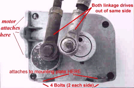
This photo shows the Gearbox of the light. It has 4 holes for mounting onto the Back Plate of the Mars Light. The motor is bolted to the side of this gearbox. Both linkages are mounted on ONE side of the gearbox and in this light, these would be facing towards the TOP of the light.
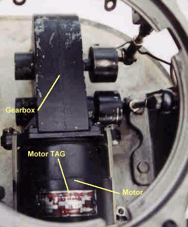
This photo is of a similar mechanism but the orientation of things is for mounting on the exterior of a locomotive. The motor and gearbox are shown, connected as described above - with the gearbox mounted to the BACK of the light and the motor mounted to the gearbox. The TAG location for identifying the motor data is shown.
Both linkages are attached to the PROJECTIONS (as above) facing the gearbox.
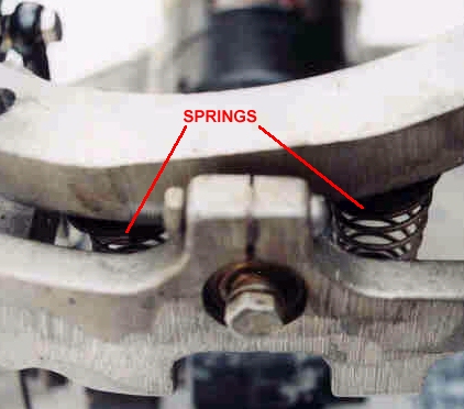
This photo shows the SPRINGS at the junction of the 2 bulb rings with the outer oval ring. There were 2 per junction for a total of 8.
Support this website by joining the Silver Rails TrainWeb Club for as little as $1 per month.
Click here for info.