This website has been archived from TrainWeb.org/gyra to TrainWeb.US/gyra.
This website has been archived from TrainWeb.org/gyra to TrainWeb.US/gyra.
This circuit was taken from the 1966 issue of "Model Railroader".

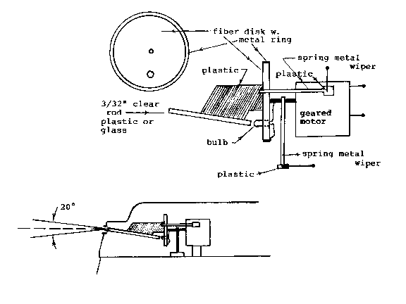
Basically, this circuit is very close to a true representation of a gyrating light. A geared minature motor is attached to a circular disk of some type of insulating material. A metal ring surrounds the disk. A hole in the disk receives a bulb. A clear plastic rod (or glass rod) of 3/32" diam. is affixed to the circular disk by way of a piece of plastic in order that the rod can be centered over the bulb in the disk. The rod is inclined at about 10° to the axis of the motor.
One wire from the bulb is affixed to the motor's shaft. The remaining wire is affixed to the metal ring surrounding the circular disk.
Spring metal wipers deliver voltage to the bulb through contact of the motor's shaft and the ring encompassing the disk.
This type of setup is well adapted for a dummy locomotive where the headlight opening used is in the nose. The article states that if the locomotive can accomodate a "rear only drive" then there might be enough room in a powered unit. The speed of the rotation would have to be adjusted to obtain the 55-60 rpm to be authentic.