This website has been archived from TrainWeb.org/gyra to TrainWeb.US/gyra.
This website has been archived from TrainWeb.org/gyra to TrainWeb.US/gyra.


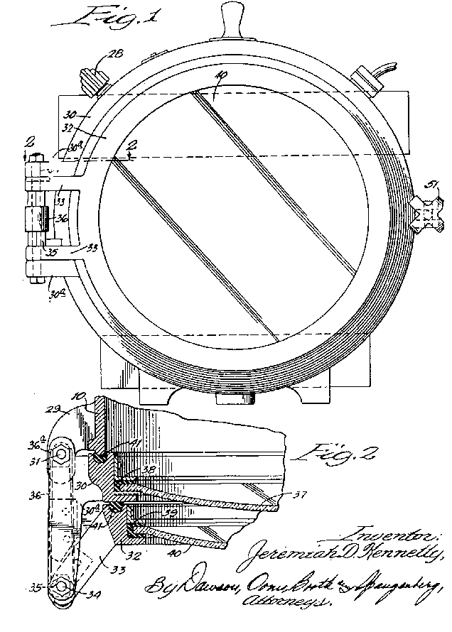
Figure 1 is a front elevation view.
Figure 2 is a detail sectional view taken at line 2.
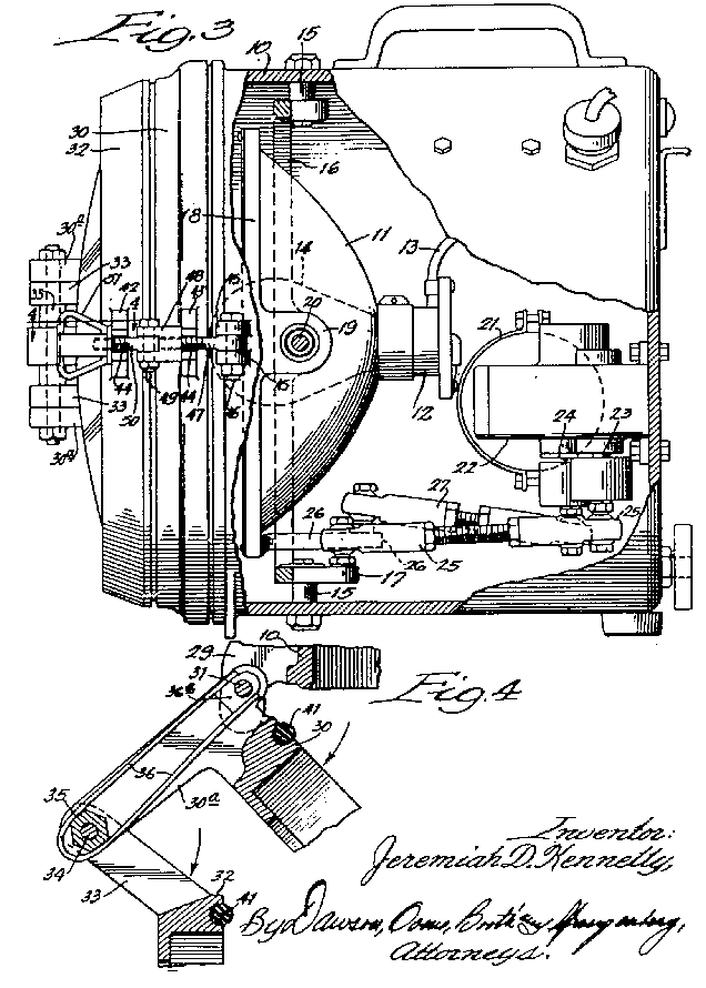
Figure 3 is a side view in elevation, a portion of the apparatus being shown in vertical
section.
Figure 4 is a detail sectional view taken at line 4 of Figure 3.
The unit can provide a stationary beam (search light) or an oscillating beam (warning light).
A selector switch 28 provides accurate control of the reflector moving mechanism so that the reflector 11 can, when desired, be stopped at a central position in which it effectively serves as a stationary search light, or set in an angular position which it again serves as a search light for illuminating a selected portion of the track or roadway or a portion of the terrain to the right or left of the roadway.
The unit is equipped with 2 lenses, 1 of which is preferably colored. Lenses can be of any desired
kind and may be equipped with prisms or clear, may be red or any other color.
The outer lens 40 can be locked into position over the inner lens 37 via nut
51 or may be swung out of the way to the side of the unit, held in this position by loop
spring's 36 engagement with the hexagonal cam 35.
The reflector assembly consists of a reflector 11 equipped with a socket 12 to
which current is supplied by conduit 13 to light bulb 14.
Studs 15 on the casing 10 support a rotatably mounted ring 16.
On one side of ring 16 there is a rearwardly extending actuating arm 17.
The reflector 11 is provided with a ring frame 18 equipped at its opposite
sides with rearwardly extending arms 19 equipped with pivot pins 20 engaging ring
16. The reflector 11 may therefore be oscillated separately while the the ring
16 is moved.
Motor 21 drives, through reduction gears contained in housing 22, a pair of
shafts 23 and 24.
Eccentrically mounted on shaft 23 is arm 25 which is pivotally connected to
actuating arm 17.
A second arm 27 is pivotally connected to arm 26 fixed to reflector ring
18.
Oscillation of the ring member 16 and the lens frame member 18
simultaneously, is designed to give a "figure 8" pattern. GN="CENTER">HOME