This website has been archived from TrainWeb.org/gyra to TrainWeb.US/gyra.
This website has been archived from TrainWeb.org/gyra to TrainWeb.US/gyra.


It was recognized that a light that merely went on and off was not sufficiently conspicuous to be distinguished from lights such as a traffic light. In addition, devices which have light sources which swing back and forth in a vertical or horizontal plane are better but the light source vanishes at the ends of the swinging movements. This creates the illusion that the light source is merely being alternately turned on and off.
The illusion created by this device, when viewed at a distance from a point in the path of the light beam, is that of a single central source of light and a second light (analogous to a satellite) revolving around it. At no time is there any extinguishing of the light as is the case in many swinging light mechanisms. The device renders a effect which is not only conspicuous but unique in its attention-getting character.
This device incorporates a light source which traverses a conical path. The simplicity of construction and minimum movement of the parts in the mechanism reduces the electric power required as well as minimizes wear.
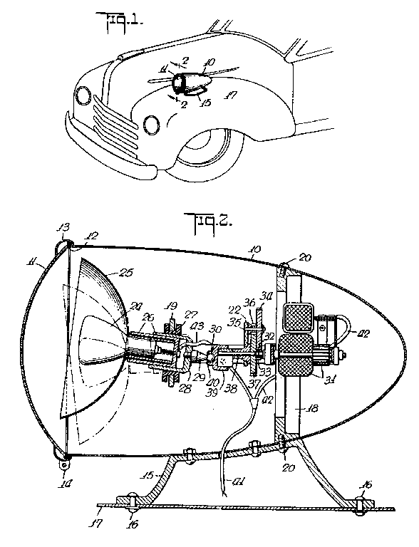
Figure 1 is a perspective view of the forward end of a vehicle illustrating the
mounting of the warning light.
Figure 2 is a longitudinal cross-sectional view through the device.
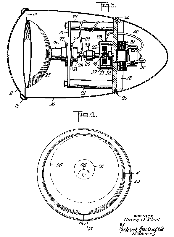
Figure 3 is a cross-sectional plan view of the device.
Figure 4 is a front view of the device without its supporting base.
An eccentric articulation is established between the drive shaft 38 and the ball 30. Actuator 39 is carried by an rigidly secured by the shaft 38 and is provided with a socket 40 within which the ball 30 is mounted. The actuator 39 is constructed so that the socket 40 lies with its center eccentric in respect to the shaft 38. Therefore, when the shaft 38 rotates, the ball 30 and the socket 40 establish a universal- joint articulation which moves the ball 30 through a small circular arc. This small circular movement imparted to the ball 30 is magnified at the front edge of the reflector due to the position of the support 27.
Energization of the motor 31 brings about a rotation of the shaft 38. The speed of rotation is reduced via reducing gears 32-37. The actuator 39 is secured to and rotates with the shaft 38, causing a corresponding circular movement to be transferred to the rear end 28 of of the stem 26 of the reflector 25. This causes a rotating of the bulb 24 and of the reflector 25. This rotation is indicated by the arrow 44 in Figure 4.
Electric lead-in wires 41 pass into the housing as indicated. One set 42 extends to the motor 31, while another set 43 extends forward to the lamp socket. [The patent does not get into the connection details of supplying current to the bulb. It is assumed that brushes with insulated contacts on a rotating disk might be used.] A suitable source of current, such as the vehicle's storage battery can be used for energizing the motor 31 as well as the lamp 24. A suitable switch on the dash board of the vehicle can be used to supply the necessary current to the warning light.