This website has been archived from TrainWeb.org/gyra to TrainWeb.US/gyra.
This website has been archived from TrainWeb.org/gyra to TrainWeb.US/gyra.


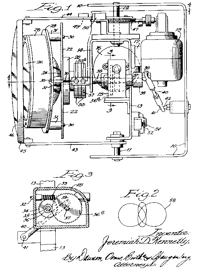
Figure 1 is a side view in elevation.
Figure 2 is a diagramatic view of the illustative pattern of light which may be produced
by this mechanism.
Figure 3 is a sectional detail view taken at line 3 of Figure 1.
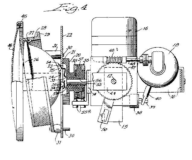
Figure 4 is a broken top plan view of the mechanism.
The light unit consists of 2 motors:
Motor 16 is responsible for the light beam pattern.
Motor 18 rotates a lens assembly in front of the projected beam.
A sealed beam headlamp unit 24 is mounted in an inclined fashion via bolts 30 and resilient sleeves 31 to plate 22 which is secured to shaft 35.
Figure 3 illustrates how the worm shaft of motor 16 drives the shaft
35 via worm gear 34.
A pinion 36 is attached to worm gear 34 which drives gear
36a mounted on shaft 37.
Shaft 37 drives a disk 38 equipped with an eccentric pin 39.
A turnbuckle link 40 connects the pin 39 and bolt head 41 carried
by stationary pin 42 which is fixed to frame 10.
As disk 38 is rotated, the eccentric pin 39 causes reciprocation of the entire
chasis mounted on the pivot shafts 11 and 12.
For supplying current to the sealed beam light 24, 2 collector rings 55 are
mounted on the hub of post 20. Leads 53 connect these collector rings 55
to the contacts 54 of the sealed beam headlamp 24. Contact brushes
55a complete the circuit for supplying current to the rotating headlamp
24.
Supported by the pivot shafts 11 and 12 are lens supporting arms 43
and 44. Arm 43 is rotatably mounted on shaft 11, while arm 44
is fixed to gear 47, rotatable on shaft 12. The arms 43 and 44
extend forward and support a lens ring 45 which carries a lens 46, which may be
plain or provided with prisms and may be of any desired color (usually red).
Motor 18 drives shaft 48 via reduction gearing. Part of this shaft is a worm
48a which meshes with worm gear 47, the rotation of which enables
the arm 44 (and accompanying assembly) to be rotated, bringing the lens 46 in
front of or out of the way of the sealed beam headlamp 24.
Limit switches 49 and 50 cut off the motor when desired position of the
asssembly is reached.
In summary, light beam is rotated conically about shaft 35 as an axis and at the same
time is displaced back and forth (or up and down) by the reciprocation caused by the turnbuckle link
40 attached to eccentric pin 39.
The precise pattern depends on the speeds of rotary and oscillatory motion.
A preferred pattern, as in Figure 2, is achieved when 1 1/2 revolutions of the shaft
35 occur in the time required for a single traverse movement of the chasis from maximum
left to maximum right. (Note: the unit can be mounted so that the oscillatory motion is perpedicular
to this, in which case it would be lowest to highest maximums.)
These rates will be governed by the sizes of the driving gears 36 and
36a.
Th preferred form of light pattern, 58 in Figure 2, is obtained when gear
36a has 3 times the diameter of gear 36.