This website has been archived from TrainWeb.org/gyra to TrainWeb.US/gyra.
This website has been archived from TrainWeb.org/gyra to TrainWeb.US/gyra.


This light unit is composed of a compact arrangement in which the light source is rotated alternately in opposite directions while the carriage supporting this mechanism is, in turn, moved laterally back and forth.
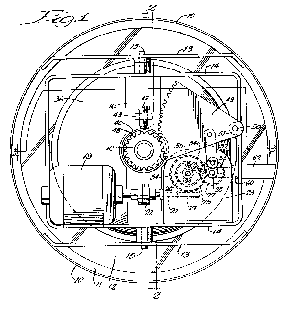
Figure 1 is a rear view in elevation.
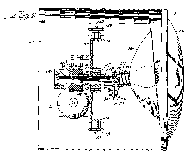
Figure 2 is a vertical sectional view. The section being taken at line 2-
2 of Figure 1.
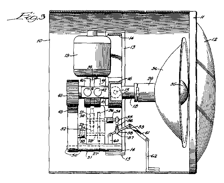
Figure 3 is a horizontal sectional view. The section being taken at line
3-3 of Figure 1.
An outer casing 10 is equipped at its forward end with a ring frame
11 which supports lens 12. Two spaced beams 13 extend
across the opposite end portions of casing 10.
An inner frame or carriage 14 is pivotally supported on cross beams
13. The carriage or frame 14 has pins 15 at opposite ends
which extend extend through bearings in the beams 13 to provide for pivotal
support of the the frame 14. The frame 14 has a "U-shaped" plate or
channel 16, centrally apertured to receive the bearings 17 for hollow
shaft 18.
Motor 19, mounted on the carriage or frame 14, has a shaft
20 provided with a worm 21. The motor shaft 20 may, if desired,
be equipped with a flexible coupling 22, as shown in Figure 1.
The socket 29 is provided with an electric light bulb 35. A reflector 36 is preferably provided and supported on the socket 29. Any suitable means is used to provide current to the light bulb 35. In this particular illustration instance, a lead 37 extends from the socket conductor liner 38 through an insulating block 39 carried by shaft 18 to the ring 40. Brush 41 supplies current to ring 40. In a similar fashion, current is supplied through brush 42 carried by the fixed support 43 to the collector ring 44. Collector ring 44, in turn, is connected to the lead 45 extending through the insulating block 46. The lead 45 connects to the central contact 47 of the light bulb 35.
Any suitable means may be used for swinging the inner frame or carriage 14
back and forth upon pins 15.
In the particular illustration instance shown, the shaft 24 has an eccentric
arm 54 attached. This eccentric arm 54 carries a pin 55 fixed to
a link 56. This link 56 is connected by a ring 57 to a ball
58 which is mounted on lever 59. The lever 59 is pivoted at one
end to an abutment 60 which is secured to frame 14. Its other end is
pivotally connected to a link 61. The link 61 is pivotally connected at its
outer end with a fixed arm 62 which is secured to the outer casing 10.
In the operation of this light unit, the light bulb socket 29 is adjusted on the
shaft 18 so that the bulb is supported off-center with respect to the shaft and
laterally of the center of the shaft. In this way, rotation of the shaft causes the light
source (and therefore the light beam) to move in a circular direction.
When set into operation, motor 19 drives via worm 21 the worm
gear 25, and therefore the shaft 24. Shaft 24 rotates the
eccentric arm 54 which causes the oscillation of the inner frame 14
about the pivot pins 15 which are carried in the frame members 13.
At the same time, the spur gear 26 on the shaft 24 drives the spur gear 27 on shaft 28. Shaft 28, by means of the eccentric arm 53, moves the link 52 back and forth and thereby causes the sector arm 49 to pivot back and forth on pivot bracket 51. The sector arm 49 meshes with gear 48 to produce oscillation of the shaft 18. This causes shaft 18 to be rotated first in one direction, and then in the other.
Therefore as the entire carriage 14 is being moved back and forth, the hollow shaft 18 is being rotated back and forth. This produces a pattern of light combining the composite rotary movement of the bulb and the lateral movement of the carriage. These movements may be varied by changing the relative proportions of the gears, sectors, angle of the light bulb socket, etc.
The movement of the light source in a back-and forth rotary direction together with the oscillation of the supporting frame, gives an unusual effect as a warning device. The reversal in rotation of the light produces a sharp contrast to the regular back-and-forth movement of the supporting carriage. The resulting effect is to immediately capture the attention of bystanders. The structure is relatively simple and effective for achieving these results.