This website has been archived from TrainWeb.org/gyra to TrainWeb.US/gyra.
This website has been archived from TrainWeb.org/gyra to TrainWeb.US/gyra.


The complete Patent (Claims and References omitted)
This invention relates generally to headlight apparatus and more particularly to an
illumination apparatus capable of being used for warning and signalling purposes or
alternatively as a stationary headlight. More particularly, the present invention includes a
novel oscillating mechanism whereby sealed beam type lamp units may be mounted on a
pivotally supported plate having an eccentric driving connection with a motor means so
that a movable beam of light may be projected through a changing pattern whenever it is
desired to employ the headlight apparatus as a warning light.
According to the general features of the present invention, a lamp support carrying
a sealed beam type lamp is pivotally supported on a self-aligning bearing or other
bearing means permitting universal movement of the lamp support about a vertical
support axis extending through the bearing. The lamp support is connected to an
electric motor or other prime mover having an eccentric driving connection by means of
an adjustable lever arm which serves to transmit an eccentric driving motion from the
motor to the lamp support to oscillate the lamp support about a bearing means so that a
movable pattern of light will be projected by the sealed beam lamp. If desired, a plurality
of sealed beam lamps may be mounted on the lamp support without impairing the
efficiency of the operation of the oscillating apparatus because the lamp support is
directly vertically supported by the bearing means.
Moreover, if a plurality of sealed beam lamp units are carried by the lamp support,
one or more of the sealed beam lamps may be appropriately screened by a suitable filter
or color screen so that a selectively colored movable beam of light may be produced by
the lamp apparatus.
The connecting rod between the eccentric driving connection of the motor and the
lamp support is also provided, according to this invention, with adjustment means so the
light pattern produced by the oscillating apparatus may be selectively varied.
The mounting arrangement of the present invention embodies a further additional
feature in that a wire conductor passage is provided directly through the bearing means
to receive wire conductors attached at one end to each sealed beam lamp unit. Since
pivotal movement of the lamp support occurs about the bearing means, flexing of the
conductor wires is minimized.
It is an object of the present invention, therefore, to provide a combination warning
light and energency headlight including an improved and simplified oscillating structure.
Another object of the present invention is to provide an oscillating structure for a
warning headlight by means of which a plurality of sealed beam type lamps nay be
oscillated and a comparartively small electric motor driving means may be employed.
Another object of the present invention is to provide a combination warning light
and stationary headlight structure comprising a reduced number of simplified elements
which may be manufactured more economically than has been heretofore possible.
Another object of this invention is to provide an oscillating structure for a warning
headlight in which the flexure of the conductor wires will be minimized.
Many other features, advantages, and additional objects of the present invention
will become manifest to those versed in the art upon making reference to the detailed
description which follows and the accompanying sheets of drawing if which preferred
embodiments of a combination warning light and stationary headlight according to the
present invention as shown.
On the drawings:
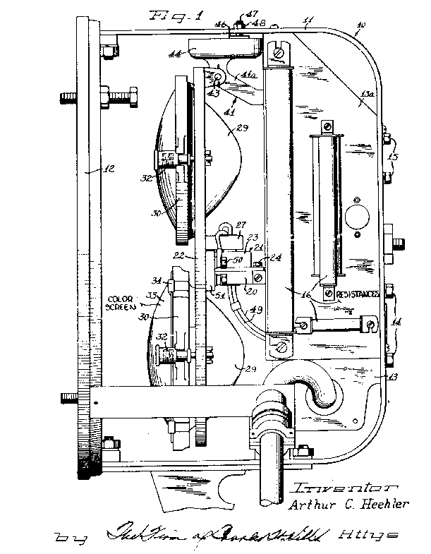
Figure 1 is a side elevational view of a combination warning light and
stationary headlight according to the present invention with the external casing removed
to show the general layout of the headlight apparatus.
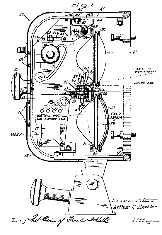
Figure 2 is a cross-sectional view with parts in elevation of a combination
warning light and stationary headlight according to the present invention.
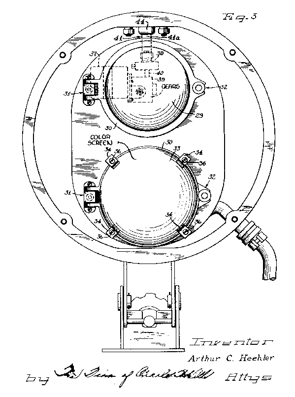
Figure 3 is a front elevation view of the headlight structure shown in
Figure 1.
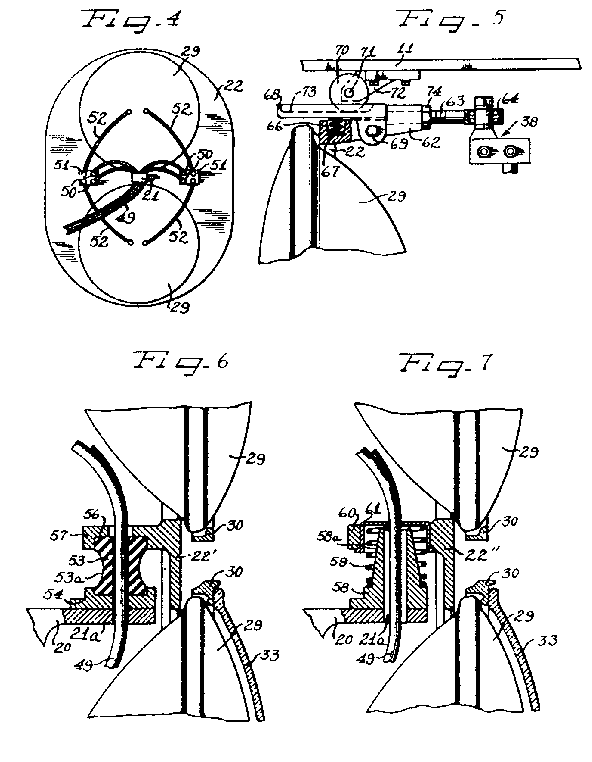
Figure 4 is a schematic illustration depicting a rear view of the lamp
support to bring out the details of the wiring arrangement whereby flexure of the
conductor wires is minimized according to the present invention.
Figure 5 is a fragmentary elevation view partly broken and with parts shown
in cross section showing an alternative form of a connecting rod between the lamp
support and the eccentric driving connection of a motor means provided in a
combination warning light and stationary headlight according to the present invention.
Figure 6 is a fragmentary cross sectional view with parts shown in
elevation of an alternative form of bearing means mounting the lamp support for
oscillatory movement.
Figure 7 is a fragmentary cross sectional view with parts shown in
elevation of yet another alternative form of bearing means for mounting a lamp support
for oscillatory movement.
As shown on the drawings:
Referring first to Figure 1, the combination warning light and stationary
headlight of present invention is indicated generally by the reference numeral 10
and includes a frame 11 conveniently formed from a "U"-shaped piece of metal
and a front ring 12 connected to the ends of the legs thereof by any suitable
fastening means.
A mounting casting 13 is securely fastened to the frame 11 by a
plurality of fasteners 14. An additional chassis 13a is also provided and
serves as a mounting base for various resistors indicated generally by the reference
numeral 16 employed in connection with the operation of the lamp apparatus. A
relay assembly indicated generally by the reference numeral 17 is also provided
and is carried on the mounting casting 13. Since the details of structure of the
control system are not believed necessary to the understanding of the principles of the
present invention, further edescription of same is believed to be unnecessary.
As will be noted on Figure 2, an open ended casing 18 is employed
to encase the entire lamp assembly and is locked to the frame 11 by a back-cover
hand wheel 19.
The mounting casting 13 is provided with a boss 20 having an
aperture 21a therethrough which extends forwardly toward the open end of of
the casing 18 and serves to support a bearing means 21 which, in turn,
is arranged to provide a vertical support axis and mounts a lamp support plate
22 for oscillatory movement about a generally vertical pivot axis extending
through the bearing means 21 and coinciding with the support axis.
In the embodiment of Figures 1, 2 and 3, the bearing means 21
includes a bearing holder 23 connected to the boss 20 by fasteners
24, the bearing holder 23 housing a conventional self-aligning pivot
bearing 26 including a curved outer race ring 26a, a plurality of shiftable
elements 26b, a curved inner race ring 26c and a hollow center post in
the form of a pivot bearing screw 26d.
The lamp support plate 22 is directly mounted on the bearing means
21 so as to be oscillatably movable about a generally vertical pivot axis,
however, in the embodiment shown in Figures 1, 2 and 3, the lamp support plate
22 is provided with a rearwardly extending boss 27 suitably apertured to
receive the pivot bearing screw 26d.
The lamp support plate 22 is provided with one or more apertures
28 each adapted to receive the bowl shaped portion of a conventional sealed
beam headlight lamp 29 therein. The lamp 29 may be retained in the
lamp support plate by a retaining ring 30 suitably hinged at one side as at
31 and latched on the other side as at 32, both the hinge 31 and
the latch 32 being spring loaded in accordance with a structural arrangement
more particularly described and claimed in the copending application of Frank X. Keegan,
Serial No. 161,050 filed May 19, 1950.
Since the apparatus of the present invention defines a particularly useful
application when employed as a combination warning light and stationary headlight on a
movable vehicle such as a locomotive, or the like, it is desirable to appropriately screen
or filter at least one of the sealed beam lamps 29 with a color screen 33
which, in this particular embodiment, comprises a disk of translucent material such as
colored glass or plastic and may be positioned in registry with one of the sealed beam
lamps 29 by means of a plurality of lens clips 34 retained on the lamp
support plate 22 by screws 36.
In order to operate the headlight apparatus of the present invention as a warning
light an oscillating mechanism including a train of mechanism to convert the rotary
motion into an oscillatory movement is provided.
The frame 11 is used to support an electric motor or other suitable prime
mover indicated at 37 suitable fasteners 15 being provided for that
purpose. An eccentric driving connection indicated 38 is provided for the motor
37. In this particular embodiment, the motor 37 is connected to a
reduction gear box 39 and a rotatable power take-off shaft 40 is provided
with an eccentric crank arm forming the eccentric driving connection 38.
A connecting rod 41 is provided between the eccentric driving connection
38 of the motor 37 and a portion of the lamp support plate 22
spaced away from the bearing means 21.
As shown in Figures 1, 2 and 3, the connecting rod is preferably provided with a
shank 41a having a stem 41b adjustably assembled therewith, the stem
41b having a rod end self-aligning bearing 42 on the end thereof
adapted to receive the crank arm of the eccentric driving connection 38. The
shank 41a of the connecting rod 41 is pivotally connected to the lamp
support plate 22 as, for example, by the pivot pin 43.
In order to stabilize the movement of the connecting rod 41 about a
predetermined pivot point and to properly translate the eccentric motion to the lamp
support plate 22, the shank 41a is preferably provided with a boss
44 having an elongated recess 45 formed therein and arranged to
receive a self-aligning guide bearing 46 carried on a pivot screw 47
secured in the frame 11 by a nut 48. The guide bearing 46 will
engage the side walls of the elongated recess 45 formed in the boss 44.
Whether the bearing means 21 mounts the lamp support plate 22
directly at the bottom of the lamp support plate or at an intermediate point afforded by
the provision of a special boss formed on the lamp support plate as, for example, the
boss 27, it will be apparent that the connection of the lamp support plate to the
eccentric drive connection 38 through the connecting rod at a pivot point
corresponding to the pin 43 spaced from the bearing means 21 will
result in oscillation of the lamp support plate 22 about the bearing means
21 so that the beam of light projected by the sealed beam lamps 29 will
be gyrated through an oscillatory path to produce a moving pattern of light.
Ordinarily the component elements of the apparatus are arranged so that the normal
beam of light projected by lamps 29 will lie on a substantially horizontal axis
corresponding generally to the casing axis. Oscillation of the lamp support plate
22 will displace the beam of light around such axis through a generally elliptical
path of traverse.
Adjustment of the stem 41b relative to the shank 41a of the
connecting rod 41 may be effected to accomodate manufacturing variations. The
relationship of the various pivot centers may thus be established in accordance with a
predetermined leverage ratio so that a desirable elliptical beam pattern may be produced.
The determination of the proper diposition of the various pivot points is taken up in
greater detail in my copending application U.S. Serial No. 191,007 filed October 19, 1950.
It should be evident that the oscillating mechanism herein provided is particularly
efficient despite the number of sealed beam lamps 29 that are mounted on the
lamp support plate 22 because all or the weight of the lamp support plate as well
as the lamps 29 is supported directly on the bearing means 21. The
force necessary to oscillate the lamp support plate 22 on the bearing means
21, therefore, will be very small and a comparatively small electric motor may be
employed as a prime mover. The absence of unusual stresses and strains afforded by
supporting the beam projecting means on a vertical pivot and support axis results in
economical operation and greatly reduced maintenance and upkeep cost.
In order to connect the sealed beam lamps 29 to a suitable source of
current supply, a plurality of electrical conductor wires 49 may be passed directly
through the passageway established by the pivot bearing screw 26d of the
bearing means 21 whereupon the ends of each of the conductors 49 may
be fastened to suitable terminal posts 50 on one or more terminal blocks
51 fastened to the rear face of the lamp support plate 22. Additional
conductor wires 52 may then be led from the terminal blocks 51 to each
of the respective sealed beam lamps 29.
The conductor wires 52, of course, together with the terminal blocks
51, oscillate with the lamp support plate 22 hence, there will be no
flexure of the additional conductor wires 52. Moreover, since the oscillation of
the lamp support plate 22 will be about a generally vertical pivot axis extending
through the bearing means 21, actual flexure of the conductor wires 49
will be substantially eliminated. This feature is especially desirable in a combination
warning light and stationary headlight since special flexure mechanisms need not be
provided and ordinary conductor wires may be employed with safety and without
incurring the need of high maintenance costs.
In Figures 6 and 7, alternative embodiments of bearing means 21
are shown, the bearing means of Figure 6 comprising a flexible elastic ring
53 made out a resilient material such as a rubber or a rubber substitute, the ring
53 being generally cylindrical in overall configuration. The ring 53 is
bottomed in a bearing support 54 connected to the boss 20 of the
mounting casting 13 and the other end of the ring 53 is received in a
complementary recess 56 formed in a boss 57 extending rearwardly from
a lamp support plate 221. The ring 53 is preferably
provided with a reduced diameter portion 53a to promote ready flexure thereof,
thereby to enhance the oscillation of the lamp support plate 221
about a vertical pivot axis extending through the hollow conductor passage found in the
center of the ring 53.
In Figure 7, the boss 20 is shown as mounting a hollow center post
58 having an upstanding generally conical portion 58a around which is
situated a coil spring 59. The lamp supporting plate 2211
is provided with a boss portion 60 suitably apertured to receive a cup-shape
retainer 61 adapted to bottom the other end of the spring 59. With the
bearing means of Figure 7, the lamp support plate 2211 is
resiliently supported by the coil spring 59 and may be freely oscillated
universally within the limits prescribed by the upstanding conical portion 58a of
the hollow center post 58 and the retainer 61.
In both of the alternative modifications, the conductor wires 49 may be
passed through the center of the bearing means, in the structural Figure 6
through the center of the ring 53 and in the structure of Figure 7 through
the hollow center post 58 and the retainer 61.
In Figure 5 is shown an alternative form of a connecting rod for connecting
the lamp support plate 22 to the eccentric driving connection 38 of
motor 37. In this form, the lamp support plate 22 is provided with a
rearwardly extending boss 62 forming the shank portion of the connecting rod.
A threaded stem 63 is received by the boss 62 and is provided with a
bearing 64 on the end thereof pivotally connectable with the crank arm of the
eccentric driving connection 38.
The boss 62 is provided with a recess 66 bottoming a spring
67 arranged to urge a guide member 68 pivoted to boss 62 by
pivot pin 69 upwardly into engagenent with a roller 70 rotatably carried
by the frame 11, a roller pin 71 supported in a bracket 72 being
provided to journal the roller 70. The guide member 68 is preferably
provided with an elongated recess 73 to receive the roller 70 and provide
a raceway therefore. A locknut 74 is provided on the stem 63 so that
various adjustment positions of the stem 63 with reference to the boss
62 may be retained in firm assembly.