This website has been archived from TrainWeb.org/gyra to TrainWeb.US/gyra.
This website has been archived from TrainWeb.org/gyra to TrainWeb.US/gyra.


This invention relates to a signal light and more particularly to an improvement in enclosed rotating signal lights of the type illustrated in US Patent 2,578,239 issued December 11, 1951.
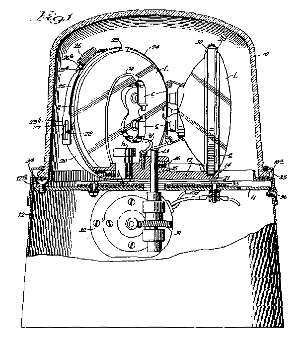
Figure 1 is a side elevational view.
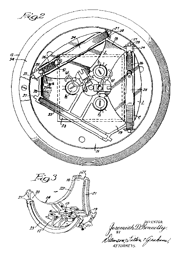
Figure 2 is a plan view with the dome and one of the lamps removed.
Figure 3 is a perspective view of the lamp support employed in the device of
Figures 1 and 2.
Dome 10 can be formed of glass or plastic and is preferably transparent although it
may be colored so as to appear red, green, etc.
On the upper end of shaft 13 within dome 10, a lamp support 14
is mounted for rotation with the shaft. Specifically, shaft 13 extends through a central
opening 15 in support 14, while support 14 is clamped to the shaft by
means of set screw 16.
The shaft 13 is driven through a gear drive 31 from motor 32, which
is mounted below platform 11 within base shell 12.
In the operation of the signal light, it is assembled as illustrated in Figures 1 and
2 of the drawing, there being provided three sealed beam lamps L, within
dome 10, as supported by holder 14 and secured therein by the expansible
elastic bands. These band members consist of two metal straps 24 and 25
secured together at their inner ends by tension spring 26. Whenever it is desired to
remove one of the lamps L, this can be done by expanding spring 26 to
release the lamp L.
in the illustration given, the springs 26 are provided with loops 26a which
releasably connect to the bands 25 by the hook ends thereof 25a. This
feature, however, is not essential for the operation of the device. It will also be noted that in the
illustration given the three recesses 21, 22 and 23 are evenly spaced around
the bottom portion 17 of lamp support 14 and are oriented to hold the sealed
beam lamps L with their lenses facing outwardly. Also it is preferred to form support
14 as a one-piece casting.