This website has been archived from TrainWeb.org/gyra to TrainWeb.US/gyra.
This website has been archived from TrainWeb.org/gyra to TrainWeb.US/gyra.


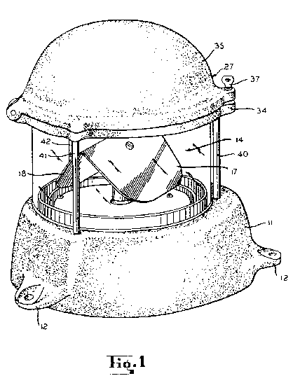
Figure 1 is a perspective view of this warning device.
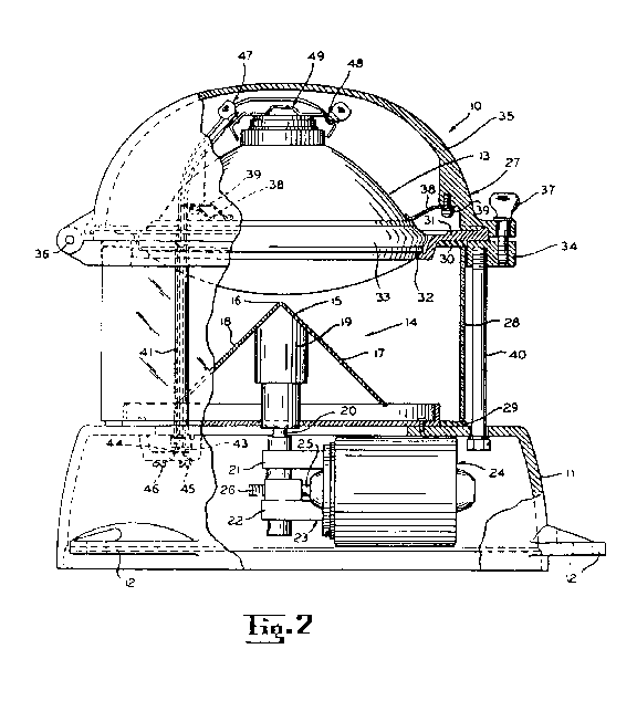
Figure 2 is an elevation view of Figure 1.
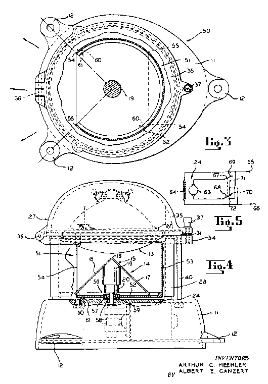
Figure 3 is a plan view.
Figure 4 is an elevation view of of a section of Figure 3.
Figure 5 is a schematic diagram illustrating the manner of energiztion of the
motor of the warning light of Figures 3 and 4.
The following relates to 2 warning lights, 10 and a modified version 50:
The warning light 10 is made up of a base 11 equipped with lugs
12 for mounting. The warning light 10 is normally mounted to a
horizontal surface.
The sealed beam unit 13 projects a beam of light downwardly against the
reflector unit 14. This reflector unit 14 is composed of a plate
15 of polished metal or similar material which is bent along the line 16 to
form 2 equal sections, 17 and 18. It is preferred that the plate be circular
and bent at right angles along a diametrical line for best results. The plate 15
has an inverted "V" configuration with sections 17 and 18 forming an
angle of 45° with the horizontal plane as well as the vertical plane. The line 16 is
located closely adjacent to the sealed beam unit 13. Half the light from the
sealed beam unit 13 is therefore directed horizontally by section 17 in
one direction, while the other half is directed 180° from this direction in the same
horizontal plane by section 18.
The reflector unit 14 is carried by the base11 for rotation about a
vertical axis. This axis coincides with the center of the sealed beam unit 13. The
plate unit 15 is secured to the upper end of a hub member 19 which is
attached to an forms part of the vertical shaft 20 wich is journalled in the
vertically supporting arms 21 and 22 of a bracket 23 which is
affixed to the electric motor 24. The motor 24 is, in turn, secured within
the base 11. The motor 24 has a drive shaft 25 which carries a
worm (not shown/not labeled). This worm meshes with a worm wheel 26 which
is affixed to the shaft 20 between the arms 21 and 22.
The sealed beam unit 13 is supported in a frame or housing 27
which is supported from the base 11 by way of a shield 28 of light
transmitting material such as glass which may be clear, red, or any other color. An
annular gasket is provided between the upper end of this shield 28 and the
housing 27. Likewise, a similar annular gasket 29 is provided between
the lower end of the shield 28 and the upper surface of the base 11.
The frame or housing 27 is also supported from the base via rods
40, 41, and 42. These rods may be in the form of bolts that are
threaded into the ring 34. One of the rods (41 in this example) is hollow
so that wires 43 and 44 may extend from the terminals 45 and
46 in the base 11 to the terminals 47 an 48,
respectively, of a connector 49 which is connected to the sealed beam unit
13.
Referring to Figures 3 and 4, the reference number 50 designates a
modified warning light. This warning light is identical in most respects to the light unit
10- A shutter 51 is comprised of a horizontal base 52 and a
vertical segmental cylindrical wall 53 wich is secured to the base 52.
The terminal edges 54 and 55 of this shutter 51 are displaced
from each other approximately 90° with respect to the axis of rotation of the unit
14 so that the wall 53 extends for approximately 270°around this axis.
The shutter 51 rotates in the direction of the shaft 20. A stop
means is employed to limit counterclockwise rotation of the shutter 51 in a
position as illustrated in Figure 3. Pin 60 from the base 52 is
arranged to engage the stop member 61 which projects upward from the base
11 to limit counterclockwise rotation of shutter 51 and the pin
60 engages stop 62 to limit clockwise rotation of the shutter 51.
Therefore, when the shaft 20 is rotated in the counterclockwise direction,
the shutter 51 will be moved to the position indicated in Figure 3 in
which the stop 61 is engaged by pin 60. With clockwise rotation, the
shutter will be rotated to the position in which the pin 60 engages with the stop
62 .
Figure 5 illustrates a circuit for reversibly energizing the motor 24
in order to accomplish this left-right beam projection. The motor 24 being of the
direct current type has an armature 63 and a field winding 64. The field
winding 64 is connected between terminals 65 and 66 which is
connected to the direct current source. The terminals of the armature 63 are
connected to moveable contacts 67 and 68 of a double pole double
throw switch. The moveable contacts 67 and 68 are selectively
engageable with fixed contacts 69 and 70 or the fixed contacts
71 and 72. The motor direction will therefore depend on the position of
the contacts 67 and 68.
This particular warning light utilizes a rotating reflector unit 14 to project a beam of light
which sweeps through 360°. An observer at any point in the path of the beam will see
one or more flashes during each rotation of the reflector unit 14.
This device utilizes a stationary light mounting with no slip rings necessary for electrical
energization of the light source. Clockwise and counterclockwise rotation of the direct current
motor make it possible to have a stop position for each rotation, thereby making it possible to
direct the beam in two alternate directions. The stop pin 60 of shutter 51 may
engage stop 62 (clockwise) or stop 61 (counterclockwise).
| 15360 Gyralite: | spec. sheets |
|---|