This
circuit is a way of powering 2, 1.5 volt micro mini 1.2mm diameter
bulbs, wired in series and used in the HO diesel's dual sealed beam
headlights or tail lights. It reduces the total current drain (and
thus the heat dissipation) compared with using a 1.5 volt regulator,
which doubles the current since the bulbs are then wired in parallel.
It uses the popular LM317T variable voltage regulator IC.
Schematic:
RED, BLACK and BLUE refer to decoder wiring standard lead designations.
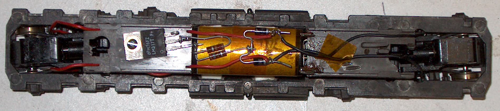
The following pictures show the circuit being installed in an Atlas Classic GP38:
(Front is to the right)
Regulator circuit without decoder wires:
Decoder installed, white wire goes to the front light bulbs, yellow to the rear light bulbs:
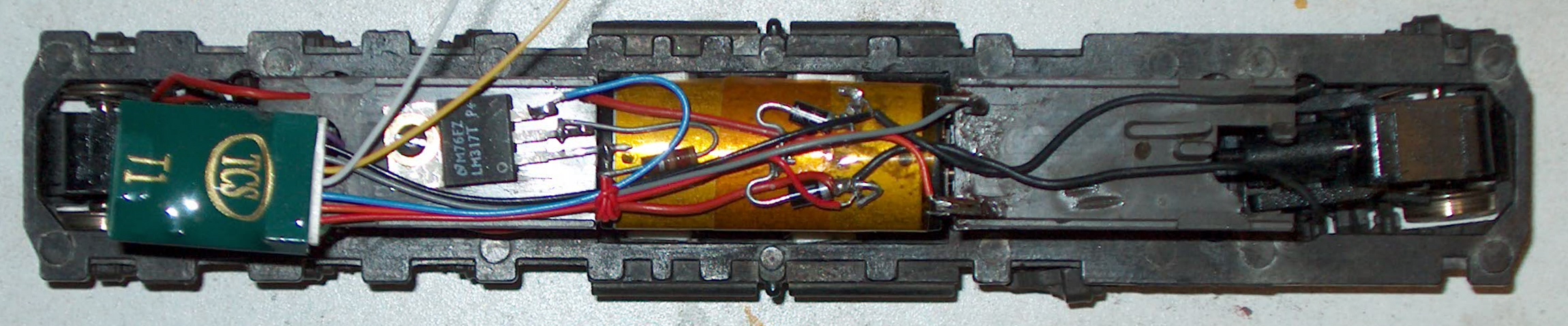
The lamp string common power leads will go to the center terminal of the LM317T instead of the BLUE wire.
With 20 ma bulbs, and the regulator circuit, the lamps and regulator
will draw a total of 50 ma if both lights are on. In contrast, a 1.5
volt regulator powered system will draw about 90 ma. underf the same
conditions.
This circuit will also provide more predictable illuminatioon with the
bulbs than using resistors in series with the bulbs, since it is
controlling the voltage presented to the bulbs, rather than the current.
Another advantage of this circuit is that wiring the bulbs in series
allows the wires that join the two bulbs together to be quite short,
reducing the number of wires that can get tangled inside the locomotive
when the shell is mounted on the frame. I usually tape those
wires inside the roof of the shell to keep the bulbs loosely in place
in the headlight housings.
-Jim Fuhrman
|