Photos - C Stock Driver's Cab
Fig.1: C Stock Cab after
refurbishment

The C Stock driver's cab in its present
condition following refurbishment. There are a number of additions to the cab since
it was first in service in 1970.
It has a new heavier cab seat and the door
controls on the driver's desk, added a couple of years after the OPO conversion in
1984. The DVA (Digitised Voice Announcement) system control is the box seen on the
front right of the driver's desk over the wire cup holder. New emergency equipment
pods added to the rear door and rear cab wall, were also added during refurbishment.
The cab light switch is still on the offside
console, meaning the driver still has to stretch over to the right to reach it when the
train is moving.
A nice big, heavy cab seat is provided, which is
a bit better that the old one, which was a real back breaker.
Back to C Stock Page
To the Top of this Page
Fig. 2: C Stock Drivers Desk
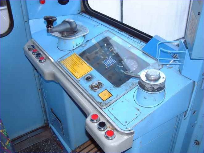
The driver's control desk of a C Stock fitted for one person
operation (OPO). Although the basic layout is the same as when the stock was built,
there have been a number of alterations.
The combined traction/brake controller (CT/BC)
is on the left. It has a spring-loaded deadman's handle. The reverser key
housing, with the key handle showing, is on the right. These have not changed.
As seen here, the cab has been "opened
up" and the train is ready to drive. The reverser key is in the off
position. The CT/BC deadman's handle, is released but, as the holding brake position
is selected, releasing the handle prevents the emergency brake applying.
The grey moulding with the black and red push
buttons for door control was added a couple of years after the introduction of OPO in 1984
to help reduce station stopping time. The push buttons are split into two open (red)
and one close (black) for each side of the train.
The Pilot Light indication is repeated twice on the driver's
desk. Its original location is on the gauge panel next to the MA Indicator and an
additional indicator on the door control panel to the left of the left side door
open/close buttons. In practice one uses the old light as the new one is obscured by
the CTBC handle when in the 'Off and Release' position.
The small steel cage on the right hand side of the window has
been added to provide a cup holder. When the stock first entered service in 1970,
the gauge panel in the centre of the control desk was regularly damaged by spilt tea and
dropped cigarette ends - smoking was allowed then. The transparent plastic cover was
added as protection very early on. The cup holder appeared at refurbishment. Photo
by District Dave.
Back to C Stock Page
To the Top of this Page
Fig. 3: C Stock Combined
Traction/Brake Controller (CT/BC)
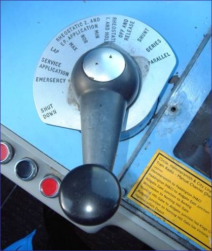
The C Stock combined traction/brake controller
showing all the positions. The controller is in the normal resting position when the
train is opened up ready to go. The handle is spring loaded against depression to
act as the driver's safety device - the famous "deadman's handle". Photo
by District Dave.
Back to C Stock Page
To the Top of this Page
Fig. 4: PA Controls
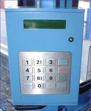
At refurbishment, the C Stock was provided with
an automatic public address system. It allows the driver to select a route and for
the PA system to announce the stations automatically as the train progresses along the
route. It is known as the DVA or Digital Voice Announcer.
The controls allow the driver to select a route,
select peak and off-peak announcements and even announce a "closed
station". Special routes can also be programmed separately.
It is also possible to select manual
announcements such as, "Let the passengers off the train first please".
Some drivers do this better than others.
The system operates by checking the distance the
train has travelled against the known distances in the DVA system. It can be
recalibrated by the operator checking the station announcement against the actual station
arrived at. Photo by District Dave.
Back to C Stock Page
To the Top of this Page
Fig. 5: Door Controls
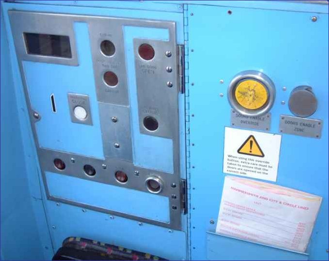
This is the original C Stock door control panel
fitted to the rear offside wall of the driver's cab. When the stock was operated by
a two-man crew, the guard worked from this panel and another, similar panel on the
nearside. The panels were positioned so that the guard could look down the train
from the rear towards the front.
The control buttons on the panel include four
along the bottom, reading from left to right, open, close, open, signal. Both the
open buttons need to be pressed to allow the doors to open. "Signal" is
used to ring the bell in the cab at the front of the train.
The two buttons on the right of the panel near
the hinges are the cab door open and close buttons. Two two buttons next to them are
the end door cut out buttons. The white button is "selective close", where
all but one pair of doors will close - to retain car heat during long layovers. The
black glass covers the pilot light indicating that all passenger doors are closed.
The light was protected in this way to make it easier to see in bright light.
Now that trains are provided with "correct
side door enable" to prevent doors being opened on the wrong side of the train, an
override is provided (the yellow button), next to the indicator lamp showing that the
doors are enabled. Photo by District Dave.
Back to C Stock Page
To the Top of this Page
Fig. 6: Offside Console
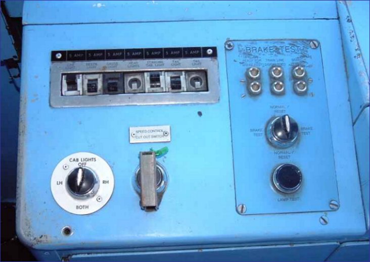
The offside control console in the C Stock
driver's cab as equipped for one-person operation. The controls provided on this
desk include MCBs for cab and front of train lighting, a speed control cut out switch and
the brake test unit.
The rotary cab light switch was added during
refurbishment to allow one or both interior lights to be selected. Before this
alteration, there was one small bulb operated directly off the MCB, which doubled as a
switch. Drivers still use this to switch on the lights as it is less difficult to
use than the rotary switch.
The brake test controls are arranged to allow
the continuity of the train line to be verified. This ensures that there is a safety
brake system available on all cars. It was installed at refurbishment but is not yet
officially used by train staff.
The speed control cut out switch is to by-pass
the 10 mph speed limit imposed for three minutes after a train is tripped.
All the on-board safety systems are provided
with emergency cut-out switches like this but they are sealed (as shown here) so that any
operation can be detected.
Below this console is a cabinet containing the
uncoupler control switches. Photo by District Dave.
Back to C Stock Page
|


