This website has been archived from TrainWeb.org/tubeprune to TrainWeb.US/tubeprune.
|
Links to pages on this site:-What is the
Underground? |
|
|||||||||||||||||||||||||||||||
| Car | Weight | Seats | Equipment | ||||||
| DM | 31.7 tons | 32 | Cab | Shoes | Traction Package | Automatic coupler | Motor Alternator | Batteries | |
| T | 20.2 tons | 32 | Shunting Controls | Automatic coupler | Compressor | ||||
To the Top of this Page
Cab and Controls
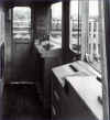 Fig 3: C Stock cab in original condition
Click on the image for the full size view and description.
The C Stock cab arrangement was originally designed for Automatic Train Operation and the arrangement of the controls is similar to the 1967 Tube Stock built for the Victoria Line. The traction/brake controller is on the left hand side of the control desk and the selector key on the right. In the centre of the desk are the air gauges and speedo with some indicator lights. It was intended that the ATO code indications would be displayed here too. After a few months in service, it was found that the display had to be protected by a transparent plastic cover, which unfortunately acts as a reflector in bright sunlight, making the display almost invisible.
At the outer end of each trailer car, there is a shunting control cabinet which is used to allow the unit to be driven from the non-driving end at reduced speed in the depot. The cabinet contains a set of miniaturised controls for selection of direction speed and braking. There is also a whistle and an air gauge. The cabinet is normally kept locked behind a panel on the left side of the car end. This equipment was only fitted during the refurbishment programme of the early 1990s. Before this time, all shunting was carried out from the driver's cab, even, when required, in reverse.
 Fig 4: Interior of the present C Stock cab
Click on the image for the full size view and description.
There have been some modifications to the stock since it entered service. The original set up for the trains was for two-person operation. The guard occupied the rear cab and controlled the doors from there. The trains were converted to OPO in 1985. The conversion consisted of minor switching modifications to the trains but required the installation of train radio and mirrors and CCTV cameras on stations.
To the Top of this Page
Modifications & Refurbishment
The C Stock has undergone a number of "mods" during its lifetime. Obviously, the refurbishment programme produced the largest number of changes but there were others carried out over the years before and since, for example, new cab seats were fitted in 1986. The cab controls were modified from time to time and a number of technical modifications were introduced over the years, particularly as a result of the OPO conversion of 1984. At that time, the original door controls on the rear walls were used by drivers at each station. For platforms on the offside, drivers had to cross the cab. For nearside platforms, some drivers used to operate the controls seated, meaning that they had to push the buttons immediately behind them with their arm behind their back. Of course, the door controls were never meant to be used in this way - they had been designed with ATO in mind. As the trains were still being driven manually, time was lost at stations as drivers had to leave their driving position to operated the doors. In 1986-7, door controls were added to the driver's control desks, see Fig 6 below.
Fig 5: Refurbished C Stock at Barbican
Click on the image for the full size view and description.
The refurbishment was carried out in a response to the Kings Cross fire of November 1987. It was decided that materials used inside cars could be further fireproofed and that the opportunity to improve the ambience should be taken at the same time. A pair of cars was sent to BREL at Derby in 1989 for an experimental refurbishment. Each car was done differently but neither was considered a sufficient improvement over the existing interior. Eventually, a new scheme by a design house known as CreActive was selected for the fleet refurbishment, which was carried out by RFS Engineering (Doncaster) Ltd. between 1990 and 1994.
During refurbishment, the glass fibre roof domes at the ends of cars were replaced by phenolic ones. This was in the belief that the fire resistance of the old roof domes was insufficient. There was a lot of fire protection hysteria in London Underground after the 1987 Kings Cross fire and this was a good example. Also during refurbishment, new ventilation slots were cut into car roofs. These were put in place for an improved forced air ventilation system was planned for the trains to replace the original system which was unreliable. It has yet to be fitted.
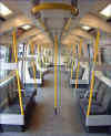 Fig
6: C Stock refurbished interior.
Click on the image for the full size view and description.
The biggest change was in the seating layout, where the transverse seating was changed to longitudinal. The new arrangement gives a wider gangway along the car and gives a more open appearance. However, the standback spaces at the doorways were lost and this has restricted the boarding and alighting times somewhat. The same number of seats is provided where the transverse seats existed but the seat width is slightly narrower. Another attempt to provide a more secure ambience inside cars is the provision of end windows. Remote trip reset and speed control after tripping (SCAT) were also been added to the stock as part of the refurbishment programme.
 Fig 7: C Stock bogie as originally delivered
Click on the image for the full size view and detailed description.
The bogies were also extensively modified during refurbishment and the original air "Metacone" suspension was removed and replaced with plain rubber suspension. The bogies were also provided with new frames.
The C Stock is now limited to 40 mph (although not governed) and most cabs have a sticker to this effect on the gauge panel. Operating instructions for the stock state that the Rate Switch (which controls acceleration) must only be used in Rate 1 and the Weak Field Flag is never raised. The combination of this tends to limit the speed, although 40 mph + is possible, for example between East Putney and Southfields and Southfields and Wimbledon, both westbound. The Rate 2 acceleration level was always too high for the stock and often caused wheelslip.
Fig 8: C Stock at S Kensington with added mouldings on the
cab corners for inter-car barriers used when the unit is coupled in the middle of a train.
Click on the image for the full size view and description.
Inter-car barriers (ICBs) have been provided to prevent persons falling between cars at stations. The barriers are black canvas hung on brackets fitted to the outer corners of the car body. They are coupled between cars on sprung attachments to allow transition on curves without creating a gap or tearing. They have become a maintenance problem and are a nuisance when coupling and uncoupling cars.
In recent years, the original half-spherical door fault indicator lights, fitted to the inner ends of cars to show operators which cars have doors open, have been replaced by electronic lamps on small rectangular housings.
To the Top of this Page
Doors
The C Stock was the first stock to have powered driver's cab doors. The doors operated in the same way as the passenger doors but were separately controlled from the cab. It was decided that the doors should have interlocks to prevent the train being moved with either cab door open. This was strange because most passengers assumed that the train would not start with the passengers doors open. This was not the case under two-person operation. Only the cab doors were interlocked in this way. This remained the system until OPO was introduced from 1984. The logic behind this regime was founded on the premise that the passenger doors did not need to be interlocked with train movement because there were two people checking all doors were closed - the guard with his "pilot light" and the driver waiting to hear the bell before starting. It worked well enough for 80 years.
Each C Stock car has four double doorways on each side. The doorway opening is built to the traditional London Underground 5 foot dimension. The door arrangement is designed to allow rapid loading and unloading at stations and is one of the better features of the stock. Door engines are the standard London Underground air operated type. The large number of door openings required that the car structure be designed with 300 mm (1 foot) deep solebars.
 Fig 9: C Stock modernised cab control desk .
Click on the image for the full size view and description.
The door controls include Selective Close, which allowed all doors except one pair on each car, to be closed. It is useful in allowing heat to be retained inside the cars when standing at terminals for a long time. Following refurbishment, door control has been fitted with "close chimes", which sound for two seconds as doors close.
Click on the image for the full size view and description.
To the Top of this Page
Public Address
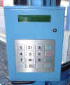 Fig 11: C Stock public address controls
Click on the image for the full size view and description.
At refurbishment, the C Stock was provided with an automatic public address system. It allows the driver to select a route and for the PA system to announce the stations automatically as the train progresses along the route. It is known as the DVA or Digital Voice Announcer.
The controls allow the driver to select a route, select peak and off-peak announcements and even announce a "closed station". Special routes can also be programmed separately.
To the Top of this Page
Equipment
The C Stock is equipped with DC traction motors using a pair of pneumatically driven camshafts, one series and one parallel, for resistance control. The traction circuit is arranged in a classic series-parallel configuration with weak field control. Each motor car in a 2-car unit has four motors, giving 50% axles motored in a train. The two motors on one bogie are permanently connected in series. The C Stock motors are type LT 117, built by Brush and drive the axle through a gear ratio of 17:114. The gear ratio was designed to give high acceleration but it sacrificed speed. The stock was originally restricted to a 45 mph top speed, only exceeded on the occasional trips to Amersham when the stock was used to cover for long gaps in the Metropolitan service during the staff shortages of the early 1970s. The pinion design to achieve this gear ratio was new and led to excessive wear, which resulted in the early renewal of the pinions.
The low voltage traction control circuits are duplicated and arranged so that one set of control circuits operates alternate motor cars along the train - i.e. two out of three - while the other set operates the third motor car. This arrangement ensures that a low voltage control circuit failure will not disable the train. The control circuit alternatives are selected by a Fault Isolating Switch (FIS) provided in the cab.
Each 2-car unit has a single reciprocating air compressor mounted under the trailer car. The compressor is of either the Westinghouse 3HC43 or Reavell TBC38Z type. The Reavell compressor is quieter. As is standard on the London Underground, compressor operation is synchronised, so that all compressors switch on and off together.
Each motor car has a motor alternator (MA) providing 230 volts AC at 850Hz for auxiliary services. The output is stepped down to 60 volts AC for the battery charger and to 115 volts AC for the main car lighting. The 60 volt AC rectifier output recharges the battery on each motor car at 50 volts DC and supplies the control circuits at that voltage. The basic system is shown in the diagram Fig 13 below.
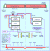 Fig 12: C Stock equipment schematic, showing
a simplified general arrangement of the on-board systems in use today. Note that
there have been a number of changes in equipment since the stock entered service.
Click on the image for the full size view.
The C Stock is equipped with four braking systems - a spring applied parking brake (SAPB), the Westinghouse air brake (used for safety systems and as a back-up, see the red train line pipe in Fig 13 above), the electro-pneumatic brake and a dynamic brake. Originally the stock had a hydraulic, manually applied parking brake, of a type also used on some BR trains of the 1960 and 70s. It was a constant source of trouble. Leaks caused the brake to apply and the train then had to be dragged to get it moving. Some very deep flats resulted from such excursions. Also, the fluid used to get everything nearby under the car sticky and caused a fire hazard. It also left a nasty slippery track when it leaked. It was replaced with SAPBs at refurbishment. The spring applied parking brake is automatic. It will apply blocks to the motored axles if brake cylinder air falls below a predetermined level (1.5 bar) while both main reservoir pressure and train line pressure falls below pre-set levels. The only snag with it is that if main reservoir air is lost on a car or unit, the cars with SAPBs applied have to be dragged with brakes applied. The wheels will turn but you shouldn't go too fast for fear of overheating them.
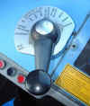 Fig 13: C Stock combined traction/brake controller (CT/BC) showing
the operating positions.
Click on the image for the full size view and description.
The Westinghouse brake works under the same principles as all air pure brakes but, on the C Stock, uses diaphragm type triple valves. The electro-pneumatic (e-p) brake is is overlaid on the Westinghouse system and is a development of the system designed for the 1967 Tube Stock ATO brake system. There are four brake application steps, each controlled by mercury retardation controllers. When the train is standing, a "holding brake" can be selected to keep a small brake cylinder pressure (1 bar) by means of a pressure switch system.
The e-p brake operates in conjunction with the dynamic brake. The traction motors are used as generators to provide a rheostatic brake on the train. The energy produced is dispersed as heat in on-board resistors. A blending system allows the rheostatic brake to provide the required level of braking on the motor cars with the e-p brake acting on trailers as necessary. When the train reaches about 20 mph, the rheostatic brake starts to fade and the air brake takes over to provide the full braking effort required. Well, that's the theory. In reality, it does work but it is a bit sloppy in control.
To the Top of this Page
Brake Testing
During its refurbishment, the C Stock was fitted with a brake test system, which is controlled from the offside console in the driver's cab (Fig 14 below). It has never been formally introduced into use by train staff. It seems that it was intended to allow trains to be prepared for service by one person but, presently, C Stock trains are officially prepared by two people. A bit strange, that.
 Fig 14: Offside console controls
Click on the image for the full size view and description.
To the Top of this Page
Maintenance
The C Stock is maintained at Hammersmith Depot, even those trains used on the District Line, which transfer to the depot from Edgware Road. The stock is now London Underground's most unreliable stock, only occasionally reaching 5,000 kms between service failures. It is usually below this. The stock has always been troublesome. There were a number of features, like the Metacone suspension and the load/weigh control which proved difficult to maintain. These were removed at refurbishment but, even so, the reliability has not improved much.
Fig 15: Rear of C Stock train on Circle Line
at Tower Hill (EB or Inner Rail).
Click on the image for the full size view.
There is also the problem of doors on this stock, which add to the reliability problems. The C Stock has 25% more doors than any other stock and doors generally account for about half all train failures. This means that the C Stock is more vulnerable to door failures. The stock also has one of the hardest duty cycles on the Underground, the Circle Line.
To the Top of this Page or to the Home Page This page upgraded 25 August 2002 Copyright © Tubeprune 2001, 2002. If you have comments or if you would like to use any part of this site for publishing or commercial reasons, please e-mail me |


